
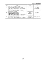


1 – 20
Chapter 1 Troubleshooting
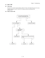
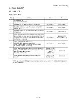
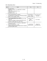
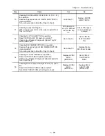
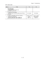
FIP1.8 Paper Jam/Exit
Step Check
Yes
No
Possible causes:
FUSER ASSY (PL8.1.20)
HVPS/MCU (PL12.1.19)
HARNESS ASSY FUSER (PL8.1.17)
MOTOR ASSY EXIT (PL10.1.15)
LVPS (PL12.1.5)
ROLL PINCH EXIT (PL10.1.23)
500 EXIT ASSY (PL10.1.2)
150 PAPER CASSETTE (PL2.1.50)
550 PAPER CASSETTE (PL4.1.50)
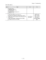
1
Checking the paper condition.
Is the paper crumpled, damaged or damp?
Replace the
paper with a new
and dry one.
Go to step 2.
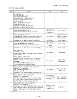
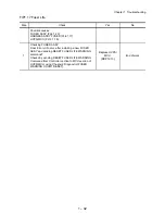
2
Checking the paper size setup.
Does the paper size in use match the size setup by
GUIDE ASSY END or by the driver on the PC?
Go to step 3.
Replace the paper,
or set up the paper
size correctly.
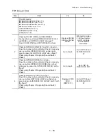
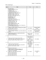
3
Does Error occur when the power is turned ON?
Go to step 4.
Go to step 6.
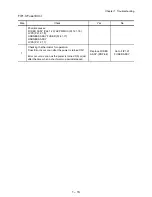
4
Checking the paper in Actuator Exit.
Is there any remaining paper in Actuator Exit?
Remove the
paper, and go to
step 5.
Go to step 8.
5
Does Error occur when the power is turned ON?
Go to step 8.
Go to step 6.
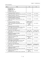
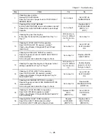
6
Run a test print.
Does Error occur?
Check using Chapter 2 Diagnostic [TEST PATTERN
MODE MENU].
Go to step 7.
End of work
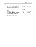
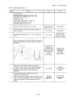
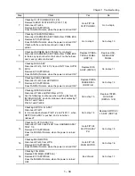
7
Checking ROLL PINCH EXIT.
Remove COVER TOP ASSY (PL1.1.7). (RRP1.4)
Is ROLL PINCH EXIT not damaged, and rotating
smoothly?
Does SPRING PINCH EXIT attach?
Turn ROLL EXIT with a finger to check.
Go to step 8.
Replace ROLL
PINCH EXIT.
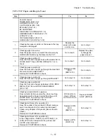
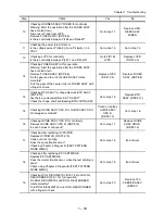
8
Checking ROLL EXIT (PL10.1.12) for rotation.
Remove EP CARTRIDGE.
Close COVER OPEN (PL1.1.2).
Turn the power ON.
Does ROLL EXIT rotate smoothly during warm up?
Go to step 9.
500 EXIT ASSY.
(RRP10.2)
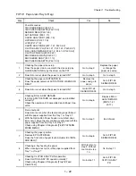
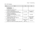
9
Checking Actuator Exit for operation.
Remove EP CARTRIDGE.
Does Actuator Exit move smoothly, when touching
Actuator Exit with a finger inserted from the exit of
FUSER ASSY, and moving it up and down?
With tool Go to
step 10. Without
tool Go to step
11.
Replace FUSER
ASSY. (RRP8.8)
10
Checking Exit Sensor for operation (1).
Remove EP CARTRIDGE.
Does the number of Sensor/Switch Check increase by
one, every time Actuator Exit is pushed and released?
Check using Chapter 2 Diagnostic [Sensor/Switch
Check].
Replace HVPS/
MCU.
(RRP12.10)
Go to step 11.
Summary of Contents for 9045N
Page 1: ...Laser Printer TallyGenicom 9045N Service Manual J20006AA ...
Page 16: ...xv Blank Page ...
Page 20: ...Chapter 1 Troubleshooting Chapter 1 Troubleshooting CONTENTS Blank Page ...
Page 88: ...1 68 Chapter 1 Troubleshooting Blank Page ...
Page 160: ...1 140 Chapter 1 Troubleshooting Blank Page ...
Page 162: ...1 142 Chapter 1 Troubleshooting Blank Page ...
Page 164: ...Chapter 2 Printer Diagnostics Chapter 2 Diagnostics CONTENTS 11 Print Summary 2 16 ...
Page 194: ...1 10 Chapter 3 Removal and Replacement Procedures RRPs RRP2 150 PAPER CASSETTE ...
Page 213: ...1 29 Chapter 3 Removal and Replacement Procedures RRPs RRP3 550 PAPER CASSETTE ...
Page 240: ...1 56 Chapter 3 Removal and Replacement Procedures RRPs RRP4 150 paper Feeder ...
Page 257: ...1 73 Chapter 3 Removal and Replacement Procedures RRPs RRP5 550 Paper Feeder ...
Page 277: ...1 93 Chapter 3 Removal and Replacement Procedures RRPs RRP6 Xerographics ...
Page 302: ...1 118 Chapter 3 Removal and Replacement Procedures RRPs RRP7 500 Paper Exit ...
Page 322: ...1 138 Chapter 3 Removal and Replacement Procedures RRPs RRP8 Frame Drive ...
Page 331: ...1 147 Chapter 3 Removal and Replacement Procedures RRPs RRP9 Electrical ...
Page 394: ...1 210 Chapter 3 Removal and Replacement Procedures RRPs ...
Page 454: ...1 270 Chapter 3 Removal and Replacement Procedures RRPs Blank Page ...
Page 459: ...4 3 Chapter 4 Plug Jack P J Connector Locations Blank Page ...
Page 465: ...4 9 Chapter 4 Plug Jack P J Connector Locations 3 2 OCT Option P J Diagram ...
Page 468: ...4 12 Chapter 4 Plug Jack P J Connector Locations Blank Page ...
Page 470: ...Chapter 5 Parts Lists Chapter 5 Parts Lists CONTENTS Blank Page ...
Page 479: ...5 9 Chapter 5 Parts List Blank Page ...
Page 483: ...5 13 Chapter 5 Parts List Blank Page ...
Page 490: ...5 20 Chapter 5 Parts List PL 7 2 500 PAPER EXIT 2 2 OPTION FACE UP TRAY ILLUSTRA TION ...
Page 496: ...5 26 Chapter 5 Parts List OPTIONS PL 10 1 OPTION DUPLEX ILLUSTRATION ...
Page 501: ...5 31 Chapter 5 Parts List Blank Page ...
Page 529: ...6 19 Chapter 6 Principles of Operation J26119AA EP CARTRIDGE BTR ASSY ...
Page 531: ...6 21 Chapter 6 Principles of Operation LD Assembly JG6121AA SOS PWB Scanner Assembly ...
Page 535: ...6 25 Chapter 6 Principles of Operation ...
Page 558: ...6 48 Chapter 6 Principles of Operation Blank Page ...
Page 584: ...7 24 Chapter 7 Wiring Diagrams and Signal Information Blank Page ...
Page 608: ...Chapter 9 ESS Options Chapter 9 Controller ESS Options Contents Blank Page ...


