


1 - 218
Chapter 3 Removal and Replacement Procedures (RRPs)
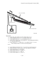
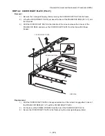
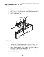
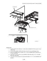
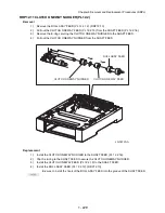
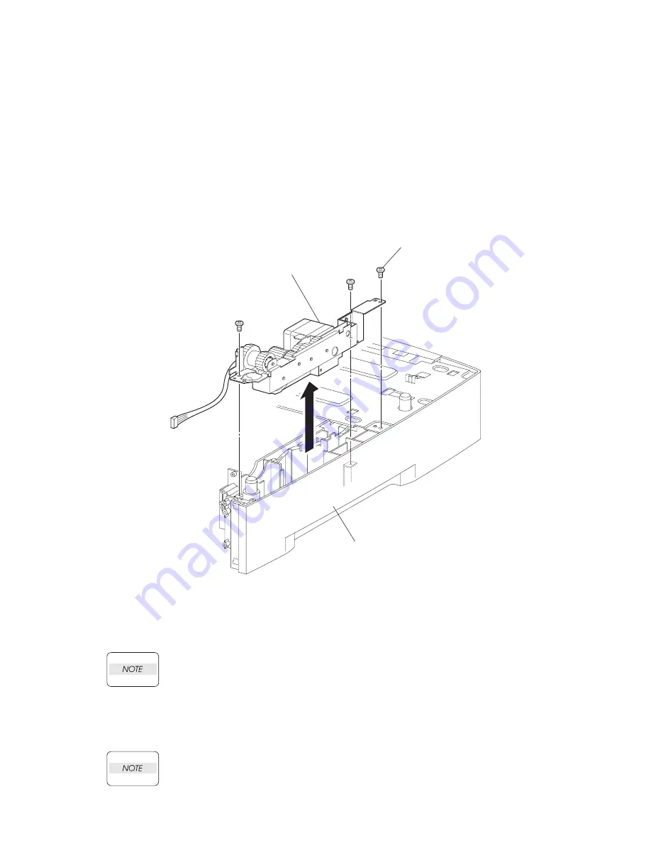
RRP12.5 DRIVE ASSY OPT FDR (PL12.1)
Removal
1)
Remove the 550 FEEDER OPTION (PL 12.2). (RRP12.1)
2)
Remove the COVER LEFT PLATE (PL 12.1.3). (RRP12.3)
3)
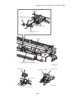
Disconnect the connector (P/J820) of the MOTOR FEEDER (PL 12.1.17) attached to the
DRIVE ASSY OPT FDR from the HARNESS ASSY FDR MOT (PL 12.1.37).
4)
Remove the 3 screws (gold tapping, 8mm x 2, silver, 6mm x 1) securing the DRIVE ASSY OPT
FDR to the FRAME CVR L550 (PL 12.1).
5)
Remove the DRIVE ASSY OPT FDR.
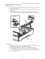
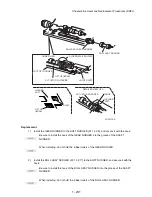
Replacement
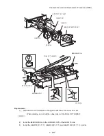
1)
Install the DRIVE ASSY OPT FDR to the FRAME CVR L550 (PL 12.1) using the 3 screws (gold
tapping, 8mm x 2, silver, 8mm x 1).
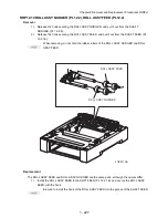
Be sure to tighten the screw (silver, 6mm) shown as Screw (A) in the figure. When tight-
ening the screws, be careful not to pinch the harness between the board and frame.
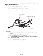
2)
Connect the connector (P/J820) of the MOTOR FEEDER (PL 12.1.17) attached to the DRIVE
ASSY OPT FDR to the HARNESS ASSY FDR MOT (PL 12.1.37).
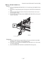
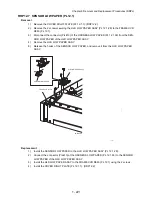
3)
Install the COVER LEFT PLATE (PL 12.1.3). (RRP12.3)
When installing the EARTH PLATE, be sure to install the tip of the EARTH PLATE under
the COVER LEFT PLATE.
DRIVE ASSY OPT FDR
(PL20.1.8)
J23506AA
FRAME CVR L550
(PL20.1.21)
Screw(A)
Summary of Contents for 9045N
Page 1: ...Laser Printer TallyGenicom 9045N Service Manual J20006AA ...
Page 16: ...xv Blank Page ...
Page 20: ...Chapter 1 Troubleshooting Chapter 1 Troubleshooting CONTENTS Blank Page ...
Page 88: ...1 68 Chapter 1 Troubleshooting Blank Page ...
Page 160: ...1 140 Chapter 1 Troubleshooting Blank Page ...
Page 162: ...1 142 Chapter 1 Troubleshooting Blank Page ...
Page 164: ...Chapter 2 Printer Diagnostics Chapter 2 Diagnostics CONTENTS 11 Print Summary 2 16 ...
Page 194: ...1 10 Chapter 3 Removal and Replacement Procedures RRPs RRP2 150 PAPER CASSETTE ...
Page 213: ...1 29 Chapter 3 Removal and Replacement Procedures RRPs RRP3 550 PAPER CASSETTE ...
Page 240: ...1 56 Chapter 3 Removal and Replacement Procedures RRPs RRP4 150 paper Feeder ...
Page 257: ...1 73 Chapter 3 Removal and Replacement Procedures RRPs RRP5 550 Paper Feeder ...
Page 277: ...1 93 Chapter 3 Removal and Replacement Procedures RRPs RRP6 Xerographics ...
Page 302: ...1 118 Chapter 3 Removal and Replacement Procedures RRPs RRP7 500 Paper Exit ...
Page 322: ...1 138 Chapter 3 Removal and Replacement Procedures RRPs RRP8 Frame Drive ...
Page 331: ...1 147 Chapter 3 Removal and Replacement Procedures RRPs RRP9 Electrical ...
Page 394: ...1 210 Chapter 3 Removal and Replacement Procedures RRPs ...
Page 454: ...1 270 Chapter 3 Removal and Replacement Procedures RRPs Blank Page ...
Page 459: ...4 3 Chapter 4 Plug Jack P J Connector Locations Blank Page ...
Page 465: ...4 9 Chapter 4 Plug Jack P J Connector Locations 3 2 OCT Option P J Diagram ...
Page 468: ...4 12 Chapter 4 Plug Jack P J Connector Locations Blank Page ...
Page 470: ...Chapter 5 Parts Lists Chapter 5 Parts Lists CONTENTS Blank Page ...
Page 479: ...5 9 Chapter 5 Parts List Blank Page ...
Page 483: ...5 13 Chapter 5 Parts List Blank Page ...
Page 490: ...5 20 Chapter 5 Parts List PL 7 2 500 PAPER EXIT 2 2 OPTION FACE UP TRAY ILLUSTRA TION ...
Page 496: ...5 26 Chapter 5 Parts List OPTIONS PL 10 1 OPTION DUPLEX ILLUSTRATION ...
Page 501: ...5 31 Chapter 5 Parts List Blank Page ...
Page 529: ...6 19 Chapter 6 Principles of Operation J26119AA EP CARTRIDGE BTR ASSY ...
Page 531: ...6 21 Chapter 6 Principles of Operation LD Assembly JG6121AA SOS PWB Scanner Assembly ...
Page 535: ...6 25 Chapter 6 Principles of Operation ...
Page 558: ...6 48 Chapter 6 Principles of Operation Blank Page ...
Page 584: ...7 24 Chapter 7 Wiring Diagrams and Signal Information Blank Page ...
Page 608: ...Chapter 9 ESS Options Chapter 9 Controller ESS Options Contents Blank Page ...


