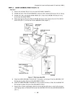
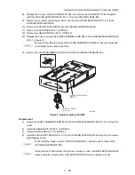


1 - 53
Chapter 3 Removal and Replacement Procedures (RRPs)
3)
Install the SUPPORT GUIDE IND together with the GUIDE INDICATOR 1 and GUIDE INDICA-
TOR 2 to the HOUSING TOP 550 (PL 12.3), and secure the GUIDE INDICATOR 1 using the 2
hooks of the HOUSING TOP 550.
4)
Slide the SUPPORT GUIDE IND (PL 3.1) along the groove of the HOUSING EXTENSION 550 to
install, and assemble the HOUSING TOP 550 and HOUSING EXTENSION 550 into 1 unit.
5)
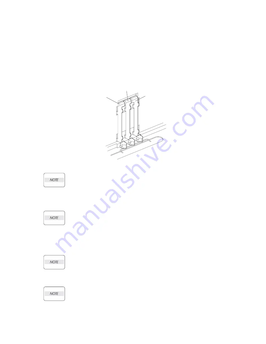
Install the HOUSING EXTENSION 550 and HOUSING TOP 550 (PL 12.3) to the HOUSING BASE
550 while pushing the LINK SW SIZE1-550 (PL 3.1), LINK SW SIZE2-550 (PL 3.1) and LINK SW
SIZE3-550 (PL 3.1) of the HOUSING BASE 550 outward as shown (Figure 3).
Figure 3. Link Size Switches
Be sure to put 2 claws on the top of the PLATE ASSEMBLY BTM under the hooks on the
HOUSING TOP 550.
6)
After assembling the HOUSING TOP 550 to the HOUSING BASE 550 using the 4 hooks, secure
them using the 2 screws (gold tapping, 8mm) on both right and left sides, as well as the 6 screws
(gold tapping, 8mm) on the back.
After tightening the screws, move the GUIDE ASSEMBLY END 550 back and forth, and
make sure that the LINK SW SIZEs operate smoothly.
7)
Insert the link lever of the GUIDE INDICATOR 1 (PL 3.1) into the hole of the PLATE ASSEMBLY
BTM.
8)
While pressing down the hook of the HOUSING TOP 550, install the GUIDE ASSEMBLY SD R550
(PL 12.3) to the HOUSING TOP 550.
After installing, make sure that the 3 claws of the GUIDE ASSEMBLY SD R550 sit cor-
rectly in the grooves of the HOUSING TOP 550.
9)
While pressing down the hook of the HOUSING TOP 550, install the GUIDE ASSEMBLY SD L550
(PL 12.3) to the HOUSING TOP 550.
After installing, make sure that the 3 claws of the GUIDE ASSEMBLY SD L550 sit cor-
rectly in the grooves of the HOUSING TOP 550.
10) Push the PLATE ASSEMBLY BTM downward to lock.
11) Install the GEAR PINION (PL 12.3) to the HOUSING TOP 550.
JG3210AA
LINK SW SIZE 1-550
(PL4.1.45)
LINK SW SIZE 2-550
(PL4.1.46)
LINK SW SIZE 3-550
(PL4.1.47)
(PL 3.1.45)
(PL 3.1.46)
(PL 3.1.47)
Summary of Contents for 9045N
Page 1: ...Laser Printer TallyGenicom 9045N Service Manual J20006AA ...
Page 16: ...xv Blank Page ...
Page 20: ...Chapter 1 Troubleshooting Chapter 1 Troubleshooting CONTENTS Blank Page ...
Page 88: ...1 68 Chapter 1 Troubleshooting Blank Page ...
Page 160: ...1 140 Chapter 1 Troubleshooting Blank Page ...
Page 162: ...1 142 Chapter 1 Troubleshooting Blank Page ...
Page 164: ...Chapter 2 Printer Diagnostics Chapter 2 Diagnostics CONTENTS 11 Print Summary 2 16 ...
Page 194: ...1 10 Chapter 3 Removal and Replacement Procedures RRPs RRP2 150 PAPER CASSETTE ...
Page 213: ...1 29 Chapter 3 Removal and Replacement Procedures RRPs RRP3 550 PAPER CASSETTE ...
Page 240: ...1 56 Chapter 3 Removal and Replacement Procedures RRPs RRP4 150 paper Feeder ...
Page 257: ...1 73 Chapter 3 Removal and Replacement Procedures RRPs RRP5 550 Paper Feeder ...
Page 277: ...1 93 Chapter 3 Removal and Replacement Procedures RRPs RRP6 Xerographics ...
Page 302: ...1 118 Chapter 3 Removal and Replacement Procedures RRPs RRP7 500 Paper Exit ...
Page 322: ...1 138 Chapter 3 Removal and Replacement Procedures RRPs RRP8 Frame Drive ...
Page 331: ...1 147 Chapter 3 Removal and Replacement Procedures RRPs RRP9 Electrical ...
Page 394: ...1 210 Chapter 3 Removal and Replacement Procedures RRPs ...
Page 454: ...1 270 Chapter 3 Removal and Replacement Procedures RRPs Blank Page ...
Page 459: ...4 3 Chapter 4 Plug Jack P J Connector Locations Blank Page ...
Page 465: ...4 9 Chapter 4 Plug Jack P J Connector Locations 3 2 OCT Option P J Diagram ...
Page 468: ...4 12 Chapter 4 Plug Jack P J Connector Locations Blank Page ...
Page 470: ...Chapter 5 Parts Lists Chapter 5 Parts Lists CONTENTS Blank Page ...
Page 479: ...5 9 Chapter 5 Parts List Blank Page ...
Page 483: ...5 13 Chapter 5 Parts List Blank Page ...
Page 490: ...5 20 Chapter 5 Parts List PL 7 2 500 PAPER EXIT 2 2 OPTION FACE UP TRAY ILLUSTRA TION ...
Page 496: ...5 26 Chapter 5 Parts List OPTIONS PL 10 1 OPTION DUPLEX ILLUSTRATION ...
Page 501: ...5 31 Chapter 5 Parts List Blank Page ...
Page 529: ...6 19 Chapter 6 Principles of Operation J26119AA EP CARTRIDGE BTR ASSY ...
Page 531: ...6 21 Chapter 6 Principles of Operation LD Assembly JG6121AA SOS PWB Scanner Assembly ...
Page 535: ...6 25 Chapter 6 Principles of Operation ...
Page 558: ...6 48 Chapter 6 Principles of Operation Blank Page ...
Page 584: ...7 24 Chapter 7 Wiring Diagrams and Signal Information Blank Page ...
Page 608: ...Chapter 9 ESS Options Chapter 9 Controller ESS Options Contents Blank Page ...


