


7 – 13
Chapter 7 Wiring Diagrams and Signal Information
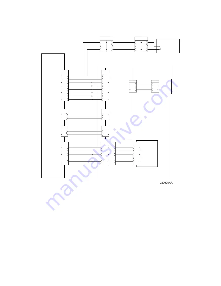
5 ROS ASSY 45-1200, INTERLOCK S/W 5V, HARNESS ASSY INTERLOCK3
P/J130
SOS
HVPS/ MCU
PL12.1.19
HARNESS ASSY
LVPS(5/6)
PL12.1.1
HARNESS ASSY ROS
PL8.1.2
2
3
4
5
6
7
8
1
2
3
4
1
7
6
5
4
3
2
1
8
5V DC
SG
/SOS
/PCONT 1
Vref
MO/DET-OUT
/PCONT2
/LDENB
XPDATA 2+
XPDATA 2-
P/J14
P/J140
1
2
P/J170
2
3
1
5VDC AFT
ROS ASSY 45-1200
PL8.1.1
LDD
Scanner
/SOS
SG
2
1
3
2
1
P/J17
XPDATA 1+
XPDATA 1-
24V DC
24V RTN/SG
/ROSMOT ON
/ROSMOT CLK
1
2
P/J160
2
1
P/J16
P/J13
4
3
2
1
5
2
2
1
3
4
3
4
1
P/J131
HARNESS ASSY
INTERLOCK3
PL8.1.12
P/J201
P/J2011
N.C.
N.C.
3
1
1
3
P/J141
2
2
N.C.
N.C.
3
1
1
3
P/J142
2
2
Summary of Contents for 9045N
Page 1: ...Laser Printer TallyGenicom 9045N Service Manual J20006AA ...
Page 16: ...xv Blank Page ...
Page 20: ...Chapter 1 Troubleshooting Chapter 1 Troubleshooting CONTENTS Blank Page ...
Page 88: ...1 68 Chapter 1 Troubleshooting Blank Page ...
Page 160: ...1 140 Chapter 1 Troubleshooting Blank Page ...
Page 162: ...1 142 Chapter 1 Troubleshooting Blank Page ...
Page 164: ...Chapter 2 Printer Diagnostics Chapter 2 Diagnostics CONTENTS 11 Print Summary 2 16 ...
Page 194: ...1 10 Chapter 3 Removal and Replacement Procedures RRPs RRP2 150 PAPER CASSETTE ...
Page 213: ...1 29 Chapter 3 Removal and Replacement Procedures RRPs RRP3 550 PAPER CASSETTE ...
Page 240: ...1 56 Chapter 3 Removal and Replacement Procedures RRPs RRP4 150 paper Feeder ...
Page 257: ...1 73 Chapter 3 Removal and Replacement Procedures RRPs RRP5 550 Paper Feeder ...
Page 277: ...1 93 Chapter 3 Removal and Replacement Procedures RRPs RRP6 Xerographics ...
Page 302: ...1 118 Chapter 3 Removal and Replacement Procedures RRPs RRP7 500 Paper Exit ...
Page 322: ...1 138 Chapter 3 Removal and Replacement Procedures RRPs RRP8 Frame Drive ...
Page 331: ...1 147 Chapter 3 Removal and Replacement Procedures RRPs RRP9 Electrical ...
Page 394: ...1 210 Chapter 3 Removal and Replacement Procedures RRPs ...
Page 454: ...1 270 Chapter 3 Removal and Replacement Procedures RRPs Blank Page ...
Page 459: ...4 3 Chapter 4 Plug Jack P J Connector Locations Blank Page ...
Page 465: ...4 9 Chapter 4 Plug Jack P J Connector Locations 3 2 OCT Option P J Diagram ...
Page 468: ...4 12 Chapter 4 Plug Jack P J Connector Locations Blank Page ...
Page 470: ...Chapter 5 Parts Lists Chapter 5 Parts Lists CONTENTS Blank Page ...
Page 479: ...5 9 Chapter 5 Parts List Blank Page ...
Page 483: ...5 13 Chapter 5 Parts List Blank Page ...
Page 490: ...5 20 Chapter 5 Parts List PL 7 2 500 PAPER EXIT 2 2 OPTION FACE UP TRAY ILLUSTRA TION ...
Page 496: ...5 26 Chapter 5 Parts List OPTIONS PL 10 1 OPTION DUPLEX ILLUSTRATION ...
Page 501: ...5 31 Chapter 5 Parts List Blank Page ...
Page 529: ...6 19 Chapter 6 Principles of Operation J26119AA EP CARTRIDGE BTR ASSY ...
Page 531: ...6 21 Chapter 6 Principles of Operation LD Assembly JG6121AA SOS PWB Scanner Assembly ...
Page 535: ...6 25 Chapter 6 Principles of Operation ...
Page 558: ...6 48 Chapter 6 Principles of Operation Blank Page ...
Page 584: ...7 24 Chapter 7 Wiring Diagrams and Signal Information Blank Page ...
Page 608: ...Chapter 9 ESS Options Chapter 9 Controller ESS Options Contents Blank Page ...


