


6 – 32
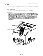
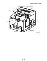
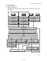
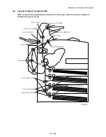
Chapter 6 Principles of Operation
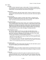
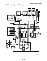
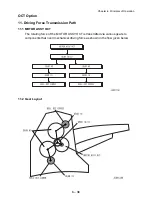
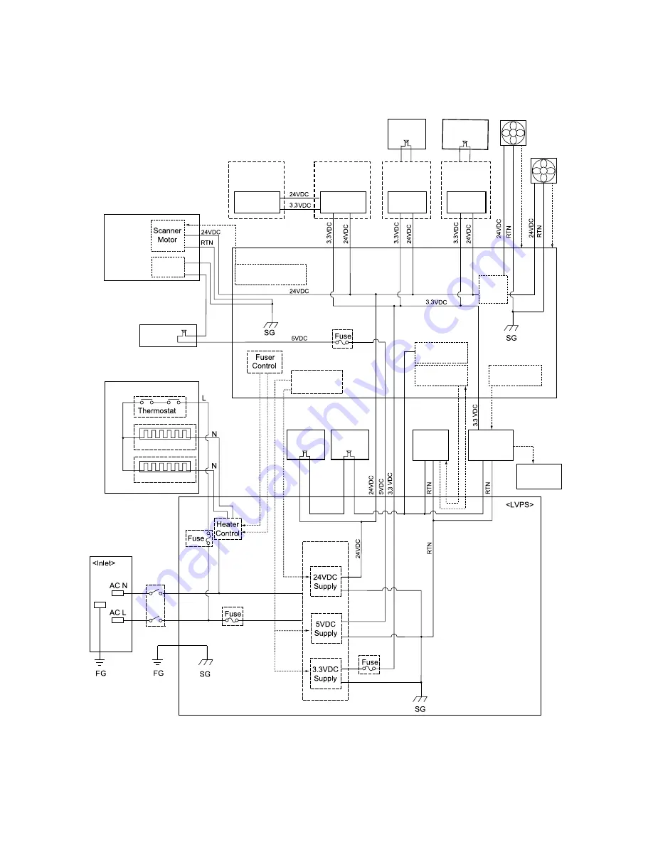
7. Schematic Diagram of Safety System
<PWBA
FEEDER550>
Option 550
Feeder
Option 550
Feeder
Option
Duplex
<PWBA
FEEDER550>
<PWBA
DUPLEX>
Option
OCT
<PWBA
OCT>
<HVPS/MCU>
LDD
<ROS ASSY>
<INTERLOCK
S/W 5V L>
<INTERLOCK
S/W 24V>
<INTERLOCK
S/W REAR>
HVPS Circuit
<PWBA
EXIT MOTOR>
<MOTOR
ASSY EXIT>
<MAIN
MOTOR>
/HEA
T ON Short
FAN MAIN
ALARM
/HEA
T ON Long
24VDC AFT
24VDC AFT
24VDC AFT
A,B,/A,/B,
24VDC AFT
<FAN MAIN>
<FAN SUB>
Heater Rod Long
Heater Rod Short
J26126AA
<SWITCH
DUPLEX>
<SW REAR
COVER>
POWER
SWITCH
Low Voltage
Generation
<FUSER ASSY>
Power
Save Control
POWER SA
VE 1
POWER SA
VE 2
FAN SUB
ALARM
MAIN MOTOR
Control
MAIN MOT
OR ON
MAIN MOT
OR
ALM
EXIT MOTOR
Control
CRU A,CRU B,INA,INB
/INA,/INB
SCANNER MOTOR
Control
SCANNER MOTOR ON,
SCANNER MOTOR CLOCK
FAN
Control
24VDC AFT
Summary of Contents for 9045N
Page 1: ...Laser Printer TallyGenicom 9045N Service Manual J20006AA ...
Page 16: ...xv Blank Page ...
Page 20: ...Chapter 1 Troubleshooting Chapter 1 Troubleshooting CONTENTS Blank Page ...
Page 88: ...1 68 Chapter 1 Troubleshooting Blank Page ...
Page 160: ...1 140 Chapter 1 Troubleshooting Blank Page ...
Page 162: ...1 142 Chapter 1 Troubleshooting Blank Page ...
Page 164: ...Chapter 2 Printer Diagnostics Chapter 2 Diagnostics CONTENTS 11 Print Summary 2 16 ...
Page 194: ...1 10 Chapter 3 Removal and Replacement Procedures RRPs RRP2 150 PAPER CASSETTE ...
Page 213: ...1 29 Chapter 3 Removal and Replacement Procedures RRPs RRP3 550 PAPER CASSETTE ...
Page 240: ...1 56 Chapter 3 Removal and Replacement Procedures RRPs RRP4 150 paper Feeder ...
Page 257: ...1 73 Chapter 3 Removal and Replacement Procedures RRPs RRP5 550 Paper Feeder ...
Page 277: ...1 93 Chapter 3 Removal and Replacement Procedures RRPs RRP6 Xerographics ...
Page 302: ...1 118 Chapter 3 Removal and Replacement Procedures RRPs RRP7 500 Paper Exit ...
Page 322: ...1 138 Chapter 3 Removal and Replacement Procedures RRPs RRP8 Frame Drive ...
Page 331: ...1 147 Chapter 3 Removal and Replacement Procedures RRPs RRP9 Electrical ...
Page 394: ...1 210 Chapter 3 Removal and Replacement Procedures RRPs ...
Page 454: ...1 270 Chapter 3 Removal and Replacement Procedures RRPs Blank Page ...
Page 459: ...4 3 Chapter 4 Plug Jack P J Connector Locations Blank Page ...
Page 465: ...4 9 Chapter 4 Plug Jack P J Connector Locations 3 2 OCT Option P J Diagram ...
Page 468: ...4 12 Chapter 4 Plug Jack P J Connector Locations Blank Page ...
Page 470: ...Chapter 5 Parts Lists Chapter 5 Parts Lists CONTENTS Blank Page ...
Page 479: ...5 9 Chapter 5 Parts List Blank Page ...
Page 483: ...5 13 Chapter 5 Parts List Blank Page ...
Page 490: ...5 20 Chapter 5 Parts List PL 7 2 500 PAPER EXIT 2 2 OPTION FACE UP TRAY ILLUSTRA TION ...
Page 496: ...5 26 Chapter 5 Parts List OPTIONS PL 10 1 OPTION DUPLEX ILLUSTRATION ...
Page 501: ...5 31 Chapter 5 Parts List Blank Page ...
Page 529: ...6 19 Chapter 6 Principles of Operation J26119AA EP CARTRIDGE BTR ASSY ...
Page 531: ...6 21 Chapter 6 Principles of Operation LD Assembly JG6121AA SOS PWB Scanner Assembly ...
Page 535: ...6 25 Chapter 6 Principles of Operation ...
Page 558: ...6 48 Chapter 6 Principles of Operation Blank Page ...
Page 584: ...7 24 Chapter 7 Wiring Diagrams and Signal Information Blank Page ...
Page 608: ...Chapter 9 ESS Options Chapter 9 Controller ESS Options Contents Blank Page ...


