25
IP Master Station Installation & Configuration
A100K10788
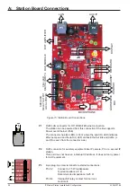
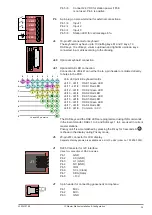
Pin 5/6
Connect 24 VDC for station power if PoE
is not used. Pin 6 is positive.
P4
6-pin plug-on screw terminal for external connections.
Pin 1/4
Input 1
Pin 2/4
Input 2
Pin 3/4
Input 3
Pin 5/6
Station LED for call message info.
J4
18-pin ZIF-connector for keyboard.
The keyboard may have up to 10 dialling keys, M and C keys, 10
DAK keys, 10 soft keys, volume up/down and light dim up/down keys
connected in a matrix according to the drawing.
J40
Optional keyboard connection.
J41
Optional DAK LED connection.
Connection to J40/J41 can either be to a pin header or soldered directly
to holes in the PCB.
J4 & J40 pin1-9 Keyboard matrix
J4/10 - J41/1 DAK1 Green LED
J4/11 - J41/2 DAK1 Red LED
J4/12 - J41/3 DAK2 Green LED
J4/13 - J41/4 DAK2 Red LED
J4/14 - J41/5 DAK3 Green LED
J4/15 - J41/6 DAK3 Red LED
J4/16 - J41/7 DAK4 Green LED
J4/17 - J41/8 DAK4 Red LED
J4/18 - J41/9 3.3 V
The DAK keys and the DAK LEDs are programmed using IND commands
in the Event Handler. DAKs 1 to 4 and Soft keys 1 to 4 are used in current
master stations.
Privacy on/off is accomplished by pressing the
C
key for 3 seconds. A
P
is shown in the display during Privacy mode.
J5
20-pin ZIF connector for LCD display.
Separate display panels are available as a kit of 5 units (order no. 100 8099 000).
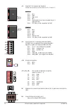
J1
RJ45 Connector for I2C interface.
Used for connection of DAK modules.
Pin 1
GND
Pin 2
A0 (GND)
Pin 3
A1 (GND)
Pin 4
NC (GND)
Pin 5
IRQ
Pin 6
SCL (Clock)
Pin 7
SDA (Data)
Pin 8
+13 V
J7
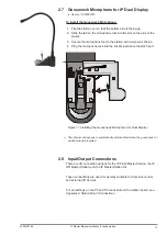
3-pin header for connecting gooseneck microphone.
Pin 1
MIC+
Pin 2
MIC-
Pin 3
GND
LED
KEY1
KEY2
KEY3
C
A
1
6
J4
0
J4
J4
1
1
9
Dim
Down
Volume
Down
Volume
Up
Dim
Up
Soft
key
10
Soft
key
9
Soft
key
8
Soft
key
7
Soft
key
6
Soft
key
5
DAK
10
DAK
9
DAK
8
DAK
3
DAK
2
DAK
1
DAK
7
DAK
6
DAK
5
DAK
4
Soft
key
4
Soft
key
3
Soft
key
2
Soft
key
1
M C
9 8
5
7
4
2
6
3
1
0
J4 and J40 pin matrix
8 7 6 5 4 3 2 1
9
8
7
6
5
4
3
2
J1
1
2
3
4
5
6
7
8
1
3
+_

