background image


35

IP Master Station Installation & Configuration

A100K10788

D: 

Restoring Factory Defaults

An IP Station may have to be reset to its original factory default settings 

if, for instance, the password to the web server is forgotten.


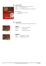
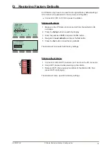
● Connect 24 VDC to P3 5/6 to power the station.

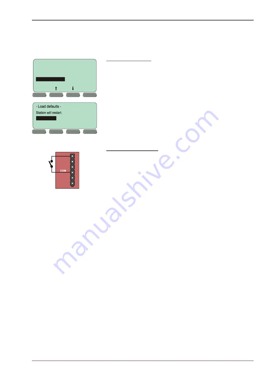
Stations with display

1.  Make sure the IP Station is disconnected from the AlphaCom XE 

exchange.

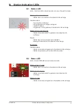
2.  Press the 

Setup

 button beneath the display 

3.  Enter the password 

1851

 and press the 

Ok

 button.

4.  Navigate to 

Load defaults

 and press the 

Sel

 button.

5.  Press the 

Sel

 button to load factory defaults.

The station will now restart with factory settings.

Stations without display

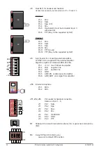
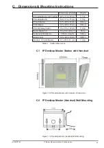
1.  Connect a switch (KEY1) between pin 1 and 4 on the P4 connector.
2.  Keep KEY1 pressed while powering up the station.
3.  Release KEY1 after precisely two blinks of the station LED, then 

press KEY1 briefly again.

The station will come up with the factory settings.

Sel

Back

- Main menu -

Station info --

>

IP settings --

>

AlphaCom Settings -->

Restart --

>

Load defaults --

>

Back

Sel

Press to set.

LED

KEY1

KEY2
KEY3

C

A

1

4

Summary of Contents for A100K10788

Page 1: ...TECHNICAL MANUAL A100K10788 installation CONFIGURATION GUIDE IP Master Stations ...

Page 2: ... of the various models of the STENTOFON IP Master Station range including accessories such as the IP DAK 48 unit gooseneck microphone and handset Revision Information Rev Date Author Status Comments 1 0 3 Feb 2010 HKL Published 1 1 6 April 2010 HKL Revised gooseneck mic illustration instructions 1 2 22 Sept 2010 ER New dimension drawing IP Flush 2 0 17 Dec 2010 HKL New display screenshots XE 2 1 1...

Page 3: ...18 3 3 3 Network Access Control 20 4 Software Upgrade 22 4 1 Prerequisites 22 4 2 Upgrade Via Station Web Server 22 4 3 Upgrade Via AlphaCom XE 23 A Station Board Connections 24 B Station Indication LEDs 27 B 1 Station LED 27 B 2 Status LED 27 B 3 Power LED 28 B 4 LAN LEDs 28 C Dimensions Mounting Instructions 29 C 1 IP Desktop Master Station with Handset 29 C 2 IP Desktop Master Handset Wall Moun...

Page 4: ...ne for Dual Display 13 Figure 12 Installing the IP DAK 48 Unit 14 Figure 13 LAN Port on IP Flush OR Master Stations 16 Figure 14 LAN Port on IP Desktop Master Station 16 Figure 15 Station Board Connections 24 Figure 16 IP Desktop Master with handset Dimensions 29 Figure 17 IP Desktop Master handset Wall Mounting 29 Figure 18 IP Desktop Master Dimensions 30 Figure 19 IP Desktop Master Wall Mounting...

Page 5: ... A100K10805 AlphaCom XE Installation Configuration Manual Figure 1 STENTOFON Security and Communication System 1 1 Features Overview The table below shows the available features of the IP Master Stations IP Desktop w handset IP Desktop IP Flush IP OR IP Dual Display Station Kit Managed data switch YES YES YES YES YES YES PoE 802 af YES YES YES YES YES YES Inline power YES YES YES YES YES YES Local...

Page 6: ...nitoring configuration and software updates over the IP network for easy maintenance of remote stations Figure 2 IP Desktop Master Station Keys Functions 1 3 IP OR Master Station item no 1008015000 The IP Operating Room OR Master Station is an advanced intercom station intended for use in operating theatres and clean rooms The chemical resistant and anti bacterial front plate is completely flat an...

Page 7: ...sh OR Master Station Keys Functions 1 5 IP DAK 48 Unit item no 1008010100 The IP DAK 48 Unit extends the IP Flush Master Station with DAK buttons and visual indicators LEDs providing the ideal solution for the control room Each DAK key is equipped with two programmable LED indicators one red and one green The LEDs can be used to show alarms notifications call requests or any other indication requi...

Page 8: ...tion and can be changed at any time Figure 4 IP Dual Display Station Keys Functions 1 7 IP Master Station Kit item no 1008093000 The IP Master Station Kit features the printed circuit board PCB as used in IP master stations It is designed to produce custom IP stations to the highest specifications and for use in the harshest of environments The IP Master Station Kit provides up to 1 5 W audio outp...

Page 9: ... 17 27 VDC Idle 4W max 8W all stations except IP Desktop Station Table 2 Station Connectors 2 2 Power Supply The IP Master Station supports Power over Ethernet PoE IEEE 802 3 a f where power can be drawn from either the spare line or signal line If PoE is not available the IP Master Station except for IP Desktop can be connected to a 24 VDC local power supply See Appendix A Station Board Connectio...

Page 10: ...andset accessory is available for the IP Flush Master Station To connect the handset Insert the RJ11 plug of the handset into the lower port of the dual RJ11 ports on the lower left of the station Figure 8 Installing the Handset STENTOFON RJ11 Plug Dual RJ11 Ports Handset IP Flush Master Station ...

Page 11: ...headsets Use headsets with an RJ11 plug To connect the headset insert the RJ11 plug of the headset into the upper port of the dual RJ11 ports on the lower left of the station Figure 9 Installing the Headset Connector pin settings for the headset can be found in Appendix A Station Board Connections STENTOFON RJ11 Plug Dual RJ11 Ports Headset IP Flush Master Station ...

Page 12: ...one s threaded stud 4 Insert the microphone s IDC socket into the upper two pins of the 3 pin header J7 located at the lower left side of the station The signal wire white should be on the top pin while the ground wire green should be on the bottom pin 5 Slide the S1 switch bottom back of station to EXT to activate the external microphone function Figure 10 Installing the Gooseneck Microphone for ...

Page 13: ...ophone jack into the socket just above the RJ45 port RJ45 Tab Slot Figure 11 Installing the Gooseneck Microphone for Dual Display The internal microphone is automatically disconnected when the gooseneck mi crophone jack is inserted 2 8 Input Output Connections There are I O connection options for the IP Flush Master Station the IP OR Master Station and the IP Master Station Kit These connections a...

Page 14: ...unit has two RJ45 ports one located on the left side and one on the right side To install the IP DAK 48 Unit 1 Plug one end of the RJ45 RJ45 cable into the RJ45 port on the right of the station when the station is viewed from the front 2 Plug the other end of the RJ45 RJ45 cable into the left when the unit is viewed from the front RJ45 port on the DAK unit Figure 12 Installing the IP DAK 48 Unit T...

Page 15: ...ngs the M key is used to insert a dot and the right middle button is used to delete a character Main menu To enter the setup menu 1 Press the Setup button on the left 2 Enter the password 1851 3 Press the Ok button A menu with five options will be displayed Use the two arrow buttons in the middle to navigate through the menu options Press the Sel button on the left to select the menu option and th...

Page 16: ... on IP Flush OR Master Stations The factory default IP address of the station is 169 254 1 100 In order for your PC to communicate with the station it is necessary to change its Internet Protocol Properties to use an IP address that is in the same range as 169 254 1 100 e g 169 254 1 1 with subnet mask 255 255 255 0 Figure 14 LAN Port on IP Desktop Master Station After the IP properties have been ...

Page 17: ... be a subscriber in the AlphaCom IP address field Enter the directory number of the station in the Directory Number field If a directory number is not entered the station will register with its MAC address The MAC address is found on the Station Info page and needs to be entered into the AlphaPro programming tool CCoIP Station IP Settings DHCP Select this option if the IP station shall receive IP ...

Page 18: ... means that noise reduction is disabled Level 1 gives a maximum noise reduction of 0 2 dB Level 2 gives a maximum noise reduction of 6 2 dB Level 3 gives a maximum noise reduction of 12 2 dB Level 4 gives a maximum noise reduction of 18 3 dB Level 5 gives a maximum noise reduction of 24 3 dB Level 6 gives a maximum noise reduction of 30 3 dB Level 7 gives a maximum noise reduction of 36 3 dB By de...

Page 19: ...lect YES or NO from the dropdown menu Port specific VLAN rules and tagging options Here it is possible to specify which VLAN ID and priority the ports should assign untagged packets to Tagged packets are not changed VLAN ID has a value range from 0 to 4094 It specifies which VLAN ID tag to add to a packet VLAN priority has a value range from 0 to 7 It specifies which VLAN priority tag to add to a ...

Page 20: ...pecified VLAN Select Remove tag or Keep tag from the dropdown menu Clicking the Add VLAN button will add the current chosen settings to the VLAN table below If a VLAN in the VLAN table already exists with the chosen VLAN ID then the settings will be updated Remove VLAN by ID Here it is possible to determine which VLAN is to be removed from the VLAN table by specifying the VLAN ID then clicking the...

Page 21: ...cation method 802 1X status Enable or disable 802 1X Username The user name that identifies a station Password The password associated with the user name Fake username The fake user name sent outside of encrypted tunnel with TTLS with PAP and PEAP with MSCHAPV2 The user name is encrypted If TTLS with PAP or PEAP with MSCHAPV2 is chosen a certificate must be uploaded to the station by clicking Brow...

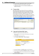
Page 22: ...eady be installed on your PC A free TFTP Server program can be downloaded from http tftpd32 jounin net Before starting the IP station upgrade procedure the TFTP Server program must be running and the folder where the software image file is located must be selected by using the Browse button in the program interface 4 2 Upgrade Via Station Web Server To upgrade the software from the station web ser...

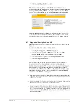
Page 23: ...tion List 4 Click Start Upgrade Process The AlphaCom XE exchange will tell the station to contact the TFTP server download the software image and carry out the upgrade A short status description of the process will be displayed in the Upgrade status column The message IPST ERROR indicates that there is no connection to the TFTP server or that the tftp_test txt file is missing from the folder The t...

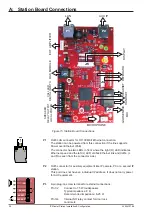
Page 24: ...or side P2 RJ45 connector for auxiliary equipment like IP camera PC or a second IP station This port does not have an individual IP address It does not carry power for AUX equipment P3 6 pin plug on screw terminal for external connections Pin 1 2 Connect to 1 5 W loudspeaker Typical impedance 8 Ω Recommended impedance 6 25 Ω Pin 3 4 Internal NO relay contact for door lock control etc P1 J9 J8 J1 J...

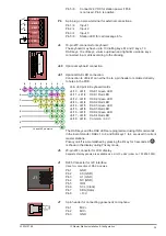
Page 25: ...reen LED J4 17 J41 8 DAK4 Red LED J4 18 J41 9 Common 3 3 V The DAK keys and the DAK LEDs are programmed using IND commands in the Event Handler DAKs 1 to 4 and Soft keys 1 to 4 are used in current master stations Privacy on off is accomplished by pressing the C key for 3 seconds A P is shown in the display during Privacy mode J5 20 pin ZIF connector for LCD display Separate display panels are avai...

Page 26: ...to the external amplifier Signal to amplifier is balanced 0dBm 600 ohm Pin 1 13 V max 500 mA to amplifier Pin 2 LSN negative line Pin 3 LSP positive line Pin 4 GND Pin 5 AMP_EN enable signal to amplifier Pin 6 AMP_ERR error signal from amplifier J10 Internal microphone Pin 1 MIC Pin 2 MIC J11 J12 J13 Pin header for handset connection Same as J8 pin 1 6 J11 Pin 1 Spk J11 Pin 2 Spk J12 Pin 1 Mic J12...

Page 27: ...cond intervals Station connected but NOT registered in the AlphaCom XE exchange Reason Station has not been programmed in AlphaPro Missing IP Station license in AlphaCom XE exchange No blinking Possible reasons Station connected and registered to the AlphaCom XE exchange Station not powered up if no other LEDs are active B 2 Status LED LED3 Bicolor SMD LED on board component side Blinking 2 red 1 ...

Page 28: ...3 V board power faulty if no other LEDs are lit Possible reasons 24 VDC or PoE not connected Faulty board B 4 LAN LEDs These LEDs are on the LAN P1 and AUX P2 RJ45 ports Left LED Steady light Ethernet connection OK Blinking Ethernet traffic No light No Ethernet connection Right LED Light 100 Mbit Ethernet connection No light 10 Mbit Ethernet connection ...

Page 29: ...aster 125 x 280 x 30 mm 0 63 kg IP Dual Display Station 72 x 270 x 139 mm 0 4 kg Master Station Kit 88 x 152 x 20 mm 250 g Gooseneck Microphone 300 mm length 0 09 kg DAK 48 Unit 125 x 280 x 30 mm 0 65 kg Handset IP Flush Master 67 x 280 x 41 mm 0 4 kg Table 3 Station Dimensions C 1 IP Desktop Master Station with Handset Figure 16 IP Desktop Master with handset Dimensions C 2 IP Desktop Master Hand...

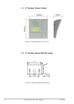
Page 30: ... A100K10788 IP Master Station Installation Configuration C 3 IP Desktop Master Station Figure 18 IP Desktop Master Dimensions C 4 IP Desktop Master Wall Mounting Figure 19 IP Desktop Master Wall Mounting ...

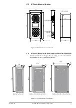
Page 31: ...ng surface mounting as well as the handset are available for the IP Flush Master Station Figure 21 IP Flush Master Backboxes 1 2 3 D1 6 5 4 7 8 9 C 0 M D2 D3 D4 280 125 32 105 260 4 2MM HOLES 105 110 236 CUT OUT HOLE RJ45 ETHERNET I O LOCAL POWER RJ11 HANDSET HEADSET www vingtor com 40 58 270 40 270 116 280 35 125 Backbox for Handset Backbox for Flush Mount Station Backbox for Surface Mount Statio...

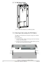
Page 32: ...ox using the four retention pegs supplied To mount the station 1 Insert the four plastic retainers into the larger and inner of the holes at each corner of the backbox 2 Align the four retention pegs with the four plastic retainers and push the station down until flush with the backbox Figure 23 Mounting the IP OR Master Station 116 270 40 70 62 62 5 x12 mm x3 Ø 21 8 mm x10 peg retainer retainer r...

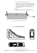
Page 33: ...ch peg gradually so that all four pegs remain at an even plane during the whole process 2 When the retention pegs are loose enough lift the station out making sure to keep the station at an even plane as it is lifted out from the backbox 1 1 Caution Do not lift the station at an angle as this may damage the pegs Figure 24 Demounting the IP OR Master Station C 9 IP Dual Display Station Figure 25 IP...

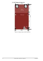
Page 34: ...aster Station Installation Configuration C 10 IP Master Station Kit Figure 26 IP Master Station Kit PCB Dimensions 82 mm 78 mm 26 mm 6 mm 88 mm 4 mm 43 mm 15 mm 78 mm 152 mm 12 mm DISPLAY on front side MIC PCB rear side ...

Page 35: ...Enter the password 1851 and press the Ok button 4 Navigate to Load defaults and press the Sel button 5 Press the Sel button to load factory defaults The station will now restart with factory settings Stations without display 1 Connect a switch KEY1 between pin 1 and 4 on the P4 connector 2 Keep KEY1 pressed while powering up the station 3 Release KEY1 after precisely two blinks of the station LED ...

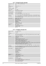
Page 36: ...d features Dual port managed data switch supporting VLAN and network access control E 2 IP OR Master Station Dimensions WxHxD 125 x 280 x 30 mm Weight 0 63 kg User interface Backlit graphical display 35 mm x 68 mm 4 function keys 4 programmable direct access keys DAK Full keypad Call indication LED Temperature Range 0 C 45 C Protection class IP 65 front access silicone must be used around edges wh...

Page 37: ...IEEE 802 1x STP IEEE 802 1d RSTP IEEE 802 1d 2004 Audio technology Telephony 3 4kHz G 711 Active noise filtering Acoustic echo cancellation Open duplex Adaptive jitter filter Volume override Audio output 1 5 Watt 75 dB 1 m from speaker Management and operation HTTPS Web configuration DHCP and static IP Remote automatic software upgrade Centralized monitoring Status LED Advanced features Dual port ...

Page 38: ...E 802 3 a f Class 0 Local 19 27 VDC power Idle 4 W max 13 W ext amplifier 6W power out to external units Connectors Ethernet 2 x RJ45 10 100 Mbit sec Handset R J11 Headset R J11 Microphone 3 pin plug Electret dynamic Loudspeaker Plugable screw terminal 1 5 W 8 Ohm 24 VDC in 1 relay out 6 pin plugable screw terminal LED 3 inputs 6 pin plugable screw terminal Gooseneck microphone 3 pin IDC Electret ...

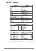
Page 39: ...14 Number or key to press during conversation Mute Unmute microphone Menu step 0 Paging with calling station number 44 Repeat absence message 1 Paging with answer 45 Inquiry Call Broker Function 2 Text message paging 46 Call Transfer 3 Voice message paging 47 Door opening 6 Remotely change message 50 Leave voice text message 7 66X Remotely read message 51 Call Back 8 Busy Notify 57 or M Search 9 B...

Page 40: ...l Norway AS The company s Quality Assurance System is certified to meet the requirements in NS EN ISO 9001 2008 Zenitel Norway AS reserves the right to modify designs and alter specifications without prior notice in pursuance of a policy of continuous improvement 2010 Zenitel Norway AS support stentofon com DOC NO support vingtor com A100K10788 ...

Reviews: