


9
IP Master Station Installation & Configuration
A100K10788
2 Installation
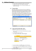
2.1 Introduction
The table below is an overview of the main connectors involved when
installing the STENTOFON IP Master Stations.
LAN
10/100 Mbps RJ-45 port for LAN (uplink) connection. Supports PoE
(802.3af). Draws power from either spare line or signal line.
AUX
10/100 Mbps RJ-45 ports for auxiliary equipment such as PC and IP
camera.
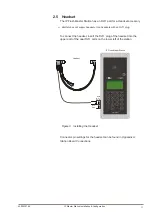
Handset Port
RJ11 (only for IP Flush Master Station and IP Master Kit)
Headset Port
RJ11 (only for IP Flush Master Station and IP Master Kit)
Input/Output
Pluggable screw terminal (all stations except IP Desktop Station)
Extension Unit (IP DAK-48)
RJ45 (only for IP Flush Master Station and IP Master Kit)
Local Power
Plugable screw terminal, 17-27 VDC Idle 4W, max. 8W (all stations
except IP Desktop Station)
Table 2 Station Connectors
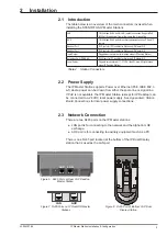
2.2 Power Supply
The IP Master Station supports Power over Ethernet (PoE, IEEE 802.3
a-f) where power can be drawn from either the spare line or signal line.
If PoE is not available, the IP Master Station (except for IP Desktop) can
be connected to a 24 VDC local power supply. See
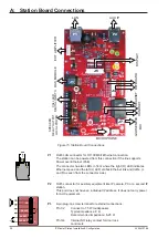
Appendix A: Station
Board Connections
for local power supply connections.
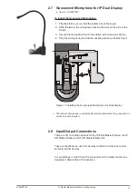
2.3
Network Connection
There are two RJ45 ports on the IP Master stations:
● LAN port is for connecting to the network and the AlphaCom XE
exchange.
● AUX port is for connecting to auxiliary equipment such as a PC.
There is one RJ45 port located at the bottom of the IP Dual Display
station that is used as the LAN port.
Figure 5 RJ45 Ports at Rear of IP Desktop
Master Station
RJ45
Figure 6 RJ45 Port at Bottom of IP Dual
Display Station
Figure 7
RJ45 Ports on IP Flush/OR Master
Stations
LAN
AUX
LAN
AUX


