24
A100K10788
IP Master Station Installation & Configuration
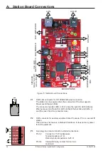
A: Station Board Connections
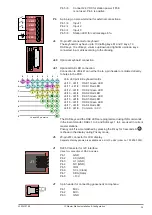
Figure 15 Station Board Connections
P1
RJ45 LAN connector for 10/100 Mbit Ethernet connection.
The station can be powered from this connection if the line supports
Power over Ethernet (PoE).
The connector has two LEDs in front where the right (R) LED indicates
Ethernet speed and the left (L) LED verifies Ethernet link and traffic. (L
and R as seen from the connector side).
P2
RJ45 connector for auxiliary equipment like IP camera, PC or a second IP
station.
This port does not have an individual IP address. It does not carry power
for AUX equipment.
P3
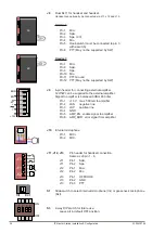
6-pin plug-on screw terminal for external connections.
Pin 1/2
Connect to 1.5 W loudspeaker.
Typical impedance: 8 Ω
Recommended impedance: 6-25 Ω.
Pin 3/4
Internal NO relay contact for door lock
control etc.
P1
J9
J8
J1
J7
P3
P4
J4
J5
J41
J40
J10
S1
S3
J12
J11
J13
P2
LAN
AUX IP
EXT
.
AMPLIFIER
KEYBOARD
GOOSENECK MIC
DISPLA
Y
DAK MODULE
HANDSET
HEADSET
LED6
LED3
LED4
MICROPHONE
CALL
LED
DIGIT
AL
INPUTS
SPEAKER
RELA
Y OUTPUT
LOCAL
POWER
L
R
LS
RELAY
0V EXT
24V EXT
+
1
6


