5-19
BVW-55 P2
Adjustment procedure
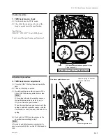
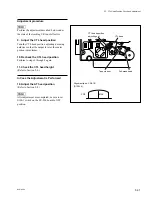
7. Tape guide height adjustment
.
In case that the tape tends to run on upper-end
side with the unit switched from PLAY to REW;
(1) Adjust T6 Guide (T tension regulator) by
turning the upper flange 90 degrees
clockwise and pressing it.
(2) Check the tape running conditions (by
performing the steps from 1 to 6.)
(3) If the tape running conditions do not meet
the specs 1 to 4, re-perform the tape guide
height adjustment. (Do not exceed 180
degrees (twice 90 degrees) when turning
the upper flange.)
.
In case that the tape tends to run on lower-end
side with the unit switched from PLAY to REW;
(1) Adjust T6 Guide (T tension regulator) by
turning the upper flange 90 degrees
counterclockwise and pulling it.
(2) Check the tape running conditions (by
performing the steps from 1 to 6.)
(3) If the tape running conditions do not meet
the specs 1 to 4, re-perform the tape guide
height adjustment. (Do not exceed 180
degrees (twice 90 degrees) when turning
the upper flange.)
8. Recheck of tape running condition
Perform steps 1 through 6 again, and check the
tape running conditions meet each specifications.
If not, perform step 7 again.
In Case the Adjustment is Performed
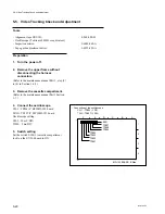
9. Video tracking check and adjustment
(Refer to Section 5-5.)
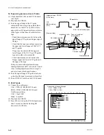
10. CTL head position check and
adjustment
(Refer to Section 5-7.)
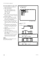
11. AT head height check and adjustment
(Refer to Section 5-9.)
12. AT head azimuth check and
adjustment
(Refer to Section 5-10.)
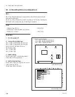
5-4. Tape Running Check and Adjustment
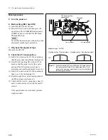
Lock knob
Driver knob
Downward
Upward
13. CTL head position check and
adjustment
(Refer to Section 5-7.)
14. AT head position check and
adjustment
(Refer to Section 5-8.)
n
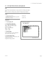
After check and adjustment are completed, be
sure to set the switch S100-1 on the SV-206
board to OFF.
Summary of Contents for BVW-55
Page 4: ......
Page 8: ......
Page 50: ...1 40 BVW 55 1 2 3 4 5 6 7 8 9 d l s d l 1 15 Fixtures and Adjustment Equipment List ...
Page 58: ......
Page 106: ......
Page 116: ......
Page 130: ......
Page 148: ......
Page 154: ......
Page 158: ......
Page 169: ...1 9 BVW 55 P2 1 2 Fixtures and Adjustment Equipment List 1 2 3 4 5 6 7 8 9 d l s d l ...
Page 176: ......
Page 272: ......
Page 384: ......
Page 392: ......
Page 396: ...1 2 BVW 55 ...
Page 666: ......
Page 705: ......
Page 752: ......
Page 780: ......
Page 805: ......
Page 848: ......
Page 856: ......
Page 870: ......
Page 884: ......
Page 904: ......
Page 909: ...5 27 b BVW 55 5 27 b CN101 CN301 CN302 CN303 CN901 MB 838 B SIDE SUFFIX 12 MB 838 MB 838 ...
Page 911: ...5 27 a BVW 55 5 27 a CN101 CN301 CN302 CN303 CN901 MB 838 B SIDE SUFFIX 11 MB 838 MB 838 ...
Page 940: ......


