


4-35
BVW-55 P2
ME gear (D)
Fig. (A)
Parallel pin
(d = 1.6 mm)
Cam gear
Hole on
mechanical
deck
1.6 mm dia. hole
Fig. (B)
Set the indication on
the pinch press cam
nearest position to
the mark.
Spec. :
Pinch press cam
Mark
*
* *
* *
Stop washer
Polywasher
Pinch press cam
Installation shaft for pinch press cam
Notch
Pinch arm slide shafts
Notch
Pinch arm slide shafts
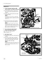
3. Pinch press cam removal
(1) Remove the stop washer using tweezers, then
remove the pinch press cam.
(2) Clean the installation shaft of the pinch press
cam with cleaning cloth moistened with
cleaning fluid.
(3) Apply grease of two grains in the size of 3
mm dia. to the
*
-marked portion of a new
pinch press cam shown in the figure. Similar-
ly, apply grease of five grains to the whole
circumference of the
**
-marked cam groove.
(4) Install the pinch press cam in the shaft while
facing the notch of the pinch press cam in the
direction shown in the figure.
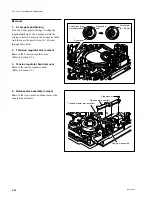
4. Pinch press cam installation/phase
adjustment
(1) Turn the ME gear(D) on the gear box clock-
wise and adjust so that the positioning hole
(1.6 mm) of the S cam gear and the reference
hole of the mechanical deck are located as
shown in figure (A).
(2) Turn the ME gear(D) counterclockwise so that
the cam gear hole and mechanical deck hole
are located as shown in figure (B), then pass
a parallel pin (d = 1.6 mm) through these
holes.
(3) Turn the ME gear(D) more counterclockwise
with the parallel pin inserted.
Confirm that the mark of the pinch press cam
and the mark of the drawer base bracket
satisfy the specifications when the cam gear
operation stops. If the specifications are not
satisfied, lift the pinch press cam slightly up
and shift the engagement of each tooth.
(4) Pull out the parallel pin (d = 1.6 mm).
4-9. Pinch Press Cam Replacement
Summary of Contents for BVW-55
Page 4: ......
Page 8: ......
Page 50: ...1 40 BVW 55 1 2 3 4 5 6 7 8 9 d l s d l 1 15 Fixtures and Adjustment Equipment List ...
Page 58: ......
Page 106: ......
Page 116: ......
Page 130: ......
Page 148: ......
Page 154: ......
Page 158: ......
Page 169: ...1 9 BVW 55 P2 1 2 Fixtures and Adjustment Equipment List 1 2 3 4 5 6 7 8 9 d l s d l ...
Page 176: ......
Page 272: ......
Page 384: ......
Page 392: ......
Page 396: ...1 2 BVW 55 ...
Page 666: ......
Page 705: ......
Page 752: ......
Page 780: ......
Page 805: ......
Page 848: ......
Page 856: ......
Page 870: ......
Page 884: ......
Page 904: ......
Page 909: ...5 27 b BVW 55 5 27 b CN101 CN301 CN302 CN303 CN901 MB 838 B SIDE SUFFIX 12 MB 838 MB 838 ...
Page 911: ...5 27 a BVW 55 5 27 a CN101 CN301 CN302 CN303 CN901 MB 838 B SIDE SUFFIX 11 MB 838 MB 838 ...
Page 940: ......