


3-31
BVW-55 P2
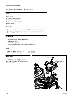
3-7. Pinch Roller Replacement
Outline
Replacement
Pinch arm assembly removal
Pinch roller replacement
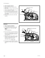
Pinch arm assembly installation
Cleaning
Operation check
Adjustment after replacement
Tape running adjustment
Precautions
.
The pinch roller can be replaced with the cassette compartment installed.
.
The following new E ring is required when replacing the pinch roller.
E ring(2.3): 7-624-105-04
Preparations
1.
Put the unit into the unthreading end state.
2.
Turn off the power.
3.
Remove the upper frame.
(Refer to the maintenance manual Part 1, Section 1-6.)
Tools
.
Torque screwdriver bit (for M1.4):
J-6325-110-A
.
Torque screwdriver (for 3 kg):
J-6325-400-A
.
Oil:
7-611-018-18
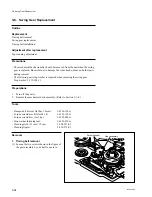
3-7. Pinch Roller Replacement
Replacement
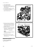
1. Pinch arm assembly removal
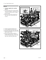
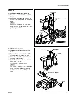
(1) Turn the manual eject knob counterclockwise
so that the notch of the pinch press cam fits
with the slider of the pinch arm assembly.
Pinch press cam
Notch
Slider
Manual eject knob
Summary of Contents for BVW-55
Page 4: ......
Page 8: ......
Page 50: ...1 40 BVW 55 1 2 3 4 5 6 7 8 9 d l s d l 1 15 Fixtures and Adjustment Equipment List ...
Page 58: ......
Page 106: ......
Page 116: ......
Page 130: ......
Page 148: ......
Page 154: ......
Page 158: ......
Page 169: ...1 9 BVW 55 P2 1 2 Fixtures and Adjustment Equipment List 1 2 3 4 5 6 7 8 9 d l s d l ...
Page 176: ......
Page 272: ......
Page 384: ......
Page 392: ......
Page 396: ...1 2 BVW 55 ...
Page 666: ......
Page 705: ......
Page 752: ......
Page 780: ......
Page 805: ......
Page 848: ......
Page 856: ......
Page 870: ......
Page 884: ......
Page 904: ......
Page 909: ...5 27 b BVW 55 5 27 b CN101 CN301 CN302 CN303 CN901 MB 838 B SIDE SUFFIX 12 MB 838 MB 838 ...
Page 911: ...5 27 a BVW 55 5 27 a CN101 CN301 CN302 CN303 CN901 MB 838 B SIDE SUFFIX 11 MB 838 MB 838 ...
Page 940: ......