6-2
BVW-55
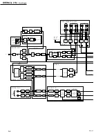
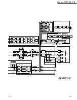
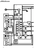
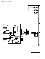
(2) Audio Signal Processing System
(CP-316, APR-42, SDI-23, AFM-16, AU-
262, HP-88)
Recording system
The analog audio signals (CH1 and CH2) input to the
AUDIO INPUT connectors (on the CP-316 board) is input
by the CP-316 board and sent to the APR-42 board.
In the CP-316 board, the Phantom power is supplied only
for overseas models.
The SDI signal input to the SDI INPUT connector is sent
to the SDI-23 board, and serial/parallel converted. After
the SDI audio signal is extracted by the audio Rx TBC
block, the SDI audio signal is converted to serial, and sent
to the APR-42 board.
In the APR-42 board, the SDI input audio signal sent from
the SDI-23 board is D/A converted, switched with the
analog input signal sent from the CP-316 board, channel
switched, channel mixed, and level controlled, etc. Then,
the CH-1 and CH-2 audio signals are sent to the AU-262
board while the CH-3 and CH-4 audio signals are sent to
the AFM-16 board.
The audio signals (CH-1/CH-2) input to the AU-262 board
are subject to DOLBY NR processing and waveform
equalization after passing through the AGC/limiter circuit.
They are then superimposed with the bias signal, and
recorded on tape as the longitudinal audio signal.
On the other hand the audio signals (CH-3/CH-4) input to
the AFM-16 board are passed through the limiter circuit
after NR processing, and then FM modulated. They are
then sent to the RP-107 board as the AFM RF signal.
Playback system
The longitudinal audio signals (CH-1/CH-2) play backed
by the AT head are waveform equalized and DOLBY NR
processed in the AU-262 board, and then level-controlled
by the AFM-16 board.
The C RF signals sent from the RP-107 board is subject to
AGC in the AU-262 board, and after only the AFM audio
signals (CH-3/CH-4) are demodulated, NR processing and
level control are performed.
The longitudinal audio signals and AFM audio signals
which are level-controlled are sent to the APR-42 board.
After the audio channel signals for line output and monitor
output are selected, they are sent to the CP-316 board, and
output from the connector panel via the 600
Z
driver. The
audio signal for monitor output can be monitored by the
headphones or speaker inside the unit.
The longitudinal audio signal and AFM audio signal sent
to the APR-42 board are A/D converted, sent to the SDI-23
board, and multiplexed with the video data by the SDI
encoder. They are then parallel/serial converted, and output
from the SDI OUT connectors on the connector panel as
the SDI signal.
Summary of Contents for BVW-55
Page 4: ......
Page 8: ......
Page 50: ...1 40 BVW 55 1 2 3 4 5 6 7 8 9 d l s d l 1 15 Fixtures and Adjustment Equipment List ...
Page 58: ......
Page 106: ......
Page 116: ......
Page 130: ......
Page 148: ......
Page 154: ......
Page 158: ......
Page 169: ...1 9 BVW 55 P2 1 2 Fixtures and Adjustment Equipment List 1 2 3 4 5 6 7 8 9 d l s d l ...
Page 176: ......
Page 272: ......
Page 384: ......
Page 392: ......
Page 396: ...1 2 BVW 55 ...
Page 666: ......
Page 705: ......
Page 752: ......
Page 780: ......
Page 805: ......
Page 848: ......
Page 856: ......
Page 870: ......
Page 884: ......
Page 904: ......
Page 909: ...5 27 b BVW 55 5 27 b CN101 CN301 CN302 CN303 CN901 MB 838 B SIDE SUFFIX 12 MB 838 MB 838 ...
Page 911: ...5 27 a BVW 55 5 27 a CN101 CN301 CN302 CN303 CN901 MB 838 B SIDE SUFFIX 11 MB 838 MB 838 ...
Page 940: ......


