2-4
BVW-55 P2
M0 -TAPE MAINTEN
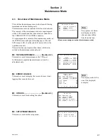
MAINTENANCE MODE
M0 : TAPE MAINTENANCE
M2 : ERROR LOGGER
M3 : OTHERS
M4 : SETUP MAINTENANCE
*
Activating the Maintenance Mode
(1) Press the
8
S201 switch (on the SY-272 board).
(2) The mode screen in the maintenance mode is superimposed on the LCD monitor.
In a
1
sub LCD, “M0-TAPE MAINTEN” is displayed.
LCD Monitor
Sub LCD
Activating the Maintenance Mode from Control Panel
The maintenance mode can be activated by the operation below when
9
S202-2 switch (on the SY-272
board) is set to ON (upper).
(1) Press the
2
MENU button once.
(Execute the setup menu mode from the operation mode.)
(2) Press the
3
SET button while pressing the
4
CTL/TC/U-BIT button.
(Execute the maintenance mode from the setup menu mode.)
(3) The mode screen in the maintenance mode is displayed on the LCD monitor.
Terminating the Maintenance Mode
(1) Press the
2
MENU button several times to display the mode screen on the LCD monitor.
The selected mode No. and title are displayed in a sub LCD.
(2) Press the
2
MENU button again to terminate the maintenance mode.
2-1. Overview of Maintenance Mode
Summary of Contents for BVW-55
Page 4: ......
Page 8: ......
Page 50: ...1 40 BVW 55 1 2 3 4 5 6 7 8 9 d l s d l 1 15 Fixtures and Adjustment Equipment List ...
Page 58: ......
Page 106: ......
Page 116: ......
Page 130: ......
Page 148: ......
Page 154: ......
Page 158: ......
Page 169: ...1 9 BVW 55 P2 1 2 Fixtures and Adjustment Equipment List 1 2 3 4 5 6 7 8 9 d l s d l ...
Page 176: ......
Page 272: ......
Page 384: ......
Page 392: ......
Page 396: ...1 2 BVW 55 ...
Page 666: ......
Page 705: ......
Page 752: ......
Page 780: ......
Page 805: ......
Page 848: ......
Page 856: ......
Page 870: ......
Page 884: ......
Page 904: ......
Page 909: ...5 27 b BVW 55 5 27 b CN101 CN301 CN302 CN303 CN901 MB 838 B SIDE SUFFIX 12 MB 838 MB 838 ...
Page 911: ...5 27 a BVW 55 5 27 a CN101 CN301 CN302 CN303 CN901 MB 838 B SIDE SUFFIX 11 MB 838 MB 838 ...
Page 940: ......

