2-15
BVW-55 P2
A0050
(1)
0
[SET]
A005
SERVO ADJUST
A005:RF SWITCHING POS.
SET
CR2-1B
ALIGNMENT TAPE
TC 00:25:00:00
PG DATA:C000
(2)
0
Insert CR2-1B
A005
SERVO ADJUST
A005:RF SWITCHING POS.
ADJUSTING......
PG DATA:BFFF
0
A005
SERVO ADJUST
A005:RF SWITCHING POS.
ADJUST COMPLETE
PG DATA:BDF7
*
*
A006:NV-RAM CONTROL
SERVO ADJUST
A005:RF SWITCHING POS.
# ADJUST INCOMPLETE #
PG DATA:C000
LCD monitor
Sub LCD
(3)
(4)
(5)
0
0
0
Confirm
[MENU]
Data save
When failing the automatic adjustment
SERVO ADJUST
A005:RF SWITCHING POS.
AUTO
PG DATA:BDF5
A005 : RF SWITCHING POS.
This menu is used to adjust the RF switching position
automatically.
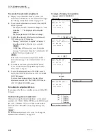
To execute the automatic adjustment
(1) Confirm that a
*
mark is assigned to the “AUTO”
display on the LCD monitor and press the SET button.
.
In a sub LCD, “A0050” is displayed.
(2) Insert alignment tape CR2-1B.
.
The adjustment is initiated when an alignment tape
is inserted. The execution time is about 15 seconds.
.
Message “ADJUSTING......” is displayed on only
the LCD monitor during adjustment.
n
If the specified cassette tape is not used, the adjust-
ment cannot be properly performed even if message
“ADJUST COMPLETE” is displayed after it is
completed.
(3) Confirm the adjustment result.
.
Message “ADJUST COMPLETE” is displayed on
the LCD monitor when the adjustment is completed
normally.
An alignment tape is ejected automatically.
.
Message “# ADJUST INCOMPLETE #” is dis-
played on the LCD monitor when no adjustment
can be performed. The adjustment is then interrupt-
ed. Refer to the “For Automatic Adjustment
Failure” on page 2-16 when this message is dis-
played.
(4) Press the MENU button to terminate the menu.
(5) To save the adjustment data in the NV-RAM of a
servo system, execute the SAVE SERVO ADJUST
data in an A006 : NV-RAM CONTROL menu.
Example of display and operation
2-2. TAPE Maintenance Mode (M0)
2-2-2. SERVO ADJUST Mode (A0)
Summary of Contents for BVW-55
Page 4: ......
Page 8: ......
Page 50: ...1 40 BVW 55 1 2 3 4 5 6 7 8 9 d l s d l 1 15 Fixtures and Adjustment Equipment List ...
Page 58: ......
Page 106: ......
Page 116: ......
Page 130: ......
Page 148: ......
Page 154: ......
Page 158: ......
Page 169: ...1 9 BVW 55 P2 1 2 Fixtures and Adjustment Equipment List 1 2 3 4 5 6 7 8 9 d l s d l ...
Page 176: ......
Page 272: ......
Page 384: ......
Page 392: ......
Page 396: ...1 2 BVW 55 ...
Page 666: ......
Page 705: ......
Page 752: ......
Page 780: ......
Page 805: ......
Page 848: ......
Page 856: ......
Page 870: ......
Page 884: ......
Page 904: ......
Page 909: ...5 27 b BVW 55 5 27 b CN101 CN301 CN302 CN303 CN901 MB 838 B SIDE SUFFIX 12 MB 838 MB 838 ...
Page 911: ...5 27 a BVW 55 5 27 a CN101 CN301 CN302 CN303 CN901 MB 838 B SIDE SUFFIX 11 MB 838 MB 838 ...
Page 940: ......


