1-6
BVW-55 P2
Cushion
CN100
CN1
DM-121 board
Reinforcement
plate (portion
A
)
Harness
Reinforcement
plate (portion
A
)
Side A
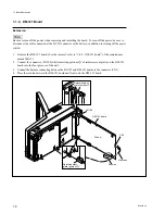
1-1-3. DM-121 Board
Extension
n
Be sure to turn off the power when removing and installing the board. To turn off the power, be sure to
disconnect the cable connected at the DC IN connector or the battery, in addition to turning off the power
switch.
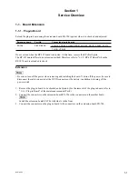
1.
Remove the DM-121 board. (For the removal, refer to “1-8-2. DM-121 board” of the maintenance
manual Part1.)
2.
Connect the connector (CN100) while inserting portions
A
of reinforcement plates on the DM-121
board into the foot grooves of the unit.
3.
Connect the harness connecting between the RP-107 and DM-121 boards to the connector (CN1).
4.
Place the cushion between the DM-121 board and floor to fix the DM-121 board.
1-1. Board Extension
Summary of Contents for BVW-55
Page 4: ......
Page 8: ......
Page 50: ...1 40 BVW 55 1 2 3 4 5 6 7 8 9 d l s d l 1 15 Fixtures and Adjustment Equipment List ...
Page 58: ......
Page 106: ......
Page 116: ......
Page 130: ......
Page 148: ......
Page 154: ......
Page 158: ......
Page 169: ...1 9 BVW 55 P2 1 2 Fixtures and Adjustment Equipment List 1 2 3 4 5 6 7 8 9 d l s d l ...
Page 176: ......
Page 272: ......
Page 384: ......
Page 392: ......
Page 396: ...1 2 BVW 55 ...
Page 666: ......
Page 705: ......
Page 752: ......
Page 780: ......
Page 805: ......
Page 848: ......
Page 856: ......
Page 870: ......
Page 884: ......
Page 904: ......
Page 909: ...5 27 b BVW 55 5 27 b CN101 CN301 CN302 CN303 CN901 MB 838 B SIDE SUFFIX 12 MB 838 MB 838 ...
Page 911: ...5 27 a BVW 55 5 27 a CN101 CN301 CN302 CN303 CN901 MB 838 B SIDE SUFFIX 11 MB 838 MB 838 ...
Page 940: ......


