2-24
BVW-55 P2
MANUAL
0
0
0
0
LCD monitor
Sub LCD
*
*
*
*
(1)
0
[Search]
+
DIAL (
2
)
PUSH SET
A231:SDI ENC VCO
Auto (Push SET button)
SDI ENC VCO 74
VCO STATUS 0
(2)
0
[SET]
PUSH SET
A231:SDI ENC VCO
Auto Adjusting ...
SDI ENC VCO 00
VCO STATUS 0
0
(omitted)
0
Confirm
[MENU]
[MENU]
Data save
PUSH SET
A231:SDI ENC VCO
Auto Adjust Complete
SDI ENC VCO 5C
VCO STATUS 1
(3)
(4)
(5)
*
A2F:NV-RAM CONTROL
AUDIO/VIDEO ADJUST MODE
A231:SDI ENC VCO
Manual
SDI ENC VCO 74
VCO STATUS 0
Example of display and operation
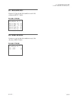
Example of A231 : SDI ENC VCO
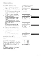
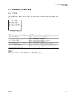
To execute the automatic adjustment
(1) Display “Auto (Push SET Button)” on the LCD
monitor and “PUSH SET” in the sub LCD referring to
the “Change of adjustment mode” on page 2-23.
(2) The automatic adjustment is executed when the SET
button is pressed.
.
The display on the LCD monitor changes to “Auto
Adjusting...”. The displayed data value also
changes.
The display in the sub LCD does not change.
(3) Confirm the automatic adjustment completion and
VCO status on the LCD monitor.
.
Message “Auto Adjust Complete” is displayed
when the automatic adjustment is completed.
n
A slight time difference may occur from when
message “Auto Adjust Complete” is displayed until
the VCO status is displayed as “1”.
n
Refer to the “For Automatic Adjustment Failure”
below when message “Auto Adjust Failure” is dis-
played.
(4) To terminate the menu, press the MENU button.
To execute the automatic adjustment again in this
menu, return to step (2).
(5) To save the adjustment data in NV-RAM, execute
SAVE ALL ADJUST DATA in an A2F : NV-RAM
CONTROL menu.
To return the adjustment data to the state before
adjustment, execute ALL DATA PREVIOUS in an
A2F : NV-RAM CONTROL menu.
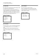
For automatic adjustment failure
It can suppose that there is something wrong with the SDI-
23 board.
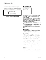
Caution during manual adjustment
When performing the manual adjustment, set the adjust-
ment data to 27.0
±
0.1 MHz at TP700 on the SDI-23 board
(for A231 : SDI ENC VCO) or at TP200 on the SDI-23
board (for A232: SDI DEC VCO) using the frequency
counter.
n
For the manual adjustment, refer to the “To change the
adjustment data manually” on page 2-21.
2-2. TAPE Maintenance Mode (M0)
2-2-4. AUDIO/VIDEO ADJUST Mode (A2)
Summary of Contents for BVW-55
Page 4: ......
Page 8: ......
Page 50: ...1 40 BVW 55 1 2 3 4 5 6 7 8 9 d l s d l 1 15 Fixtures and Adjustment Equipment List ...
Page 58: ......
Page 106: ......
Page 116: ......
Page 130: ......
Page 148: ......
Page 154: ......
Page 158: ......
Page 169: ...1 9 BVW 55 P2 1 2 Fixtures and Adjustment Equipment List 1 2 3 4 5 6 7 8 9 d l s d l ...
Page 176: ......
Page 272: ......
Page 384: ......
Page 392: ......
Page 396: ...1 2 BVW 55 ...
Page 666: ......
Page 705: ......
Page 752: ......
Page 780: ......
Page 805: ......
Page 848: ......
Page 856: ......
Page 870: ......
Page 884: ......
Page 904: ......
Page 909: ...5 27 b BVW 55 5 27 b CN101 CN301 CN302 CN303 CN901 MB 838 B SIDE SUFFIX 12 MB 838 MB 838 ...
Page 911: ...5 27 a BVW 55 5 27 a CN101 CN301 CN302 CN303 CN901 MB 838 B SIDE SUFFIX 11 MB 838 MB 838 ...
Page 940: ......


