Sitex SP38 Installation and Operation
Document PN
29010101
V2r0
- 4
9
-
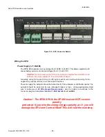
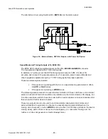
All three outputs are logic-level, open-drain outputs direct from the SPU’s microcontroller,
and must be used only within the following voltage/current limits:
Each output requires its own external pull-up resistor, which
must
be wired
only
to the SPU’s logic power supply (5 VDC, created by a linear regulator on the
SPU, and available at the V+ pin of
J12
), and to the external alarm, lamp and/or
control circuit. The resistor value plus the impedance of the load must total
no
less
than 3K3 Ohms (to limit the current into the pin in the “0 V” state to
less
than 1.6 mA
).
If needed, the SPU’s ground reference for these signals is on the GND pin of
J6
.
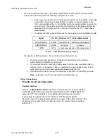
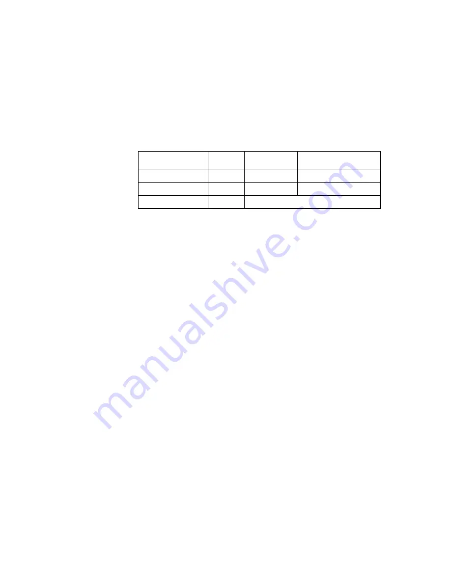
Signal
J12 Pin
When at 0 V
When Open-circuit
WORK MODE
WORK
Normal mode
WORK mode engaged
SPEED MODE
HI SPD
Lo Speed
Hi Speed
1PPS
1PPS
(1 pulse per second, ~50% duty cycle)
Table 2 – Speed Mode and Timing Outputs
All outputs are ESD-protected – but you still must use them with care:
Do not use more than about 0.5 m of cable to connect them to the external
alarm/indicator or stabilizer-control circuit.
If you must connect to something farther away than that, use a suitable buffer or
isolator circuit – a transistor, a relay or (preferred) an opto-isolator block. With a
relay, be sure to wire a fly back-suppressor diode across the coil.
If shielded wire is used, connect the shield only at the SPU – to the GND pin of
J6
.
Note
: unused pins on J12 are reserved for possible future use.
Other Connections
Thruster Assist steering option
Thruster Interface
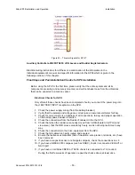
The
J11 – THRUSTER I’ FACE
connector is used with the CT7 Thru
ster Interface
in SPU PN 201400002 or as analog thruster assistance
S
PU-T PN20140006. For
using with CT7, the receptacle is not supplied with a mating plug, since the
required plug is supplied with the CT7. Refer to CT7 Manual for details.
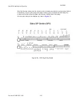
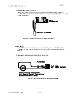
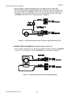
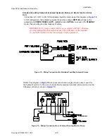
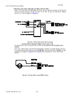
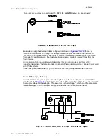
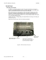
Figure 25 shows the analog thruster assistance outputs in SPU-T
ster Interface. The
receptacle is not supplied with a mating plug, since the required plug is supplied
with the CT7
.
Installation
Summary of Contents for SP38 Autopilot
Page 2: ......
Page 14: ...Sitex SP38 Installation and Operation Document PN 29010101 V2r0 13 ...
Page 15: ...Sitex SP38 Installation and Operation Document PN 29010101 V2r0 14 Introduction ...
Page 16: ...Sitex SP38 Installation and Operation Document PN 29010101 V2r0 15 ...
Page 26: ...Sitex SP38 Installation and Operation Document PN 29010101 V2r0 25 ...
Page 35: ...Sitex SP38 Installation and Operation Document PN 29010101 V2r0 34 Installation ...
Page 36: ...Sitex SP38 Installation and Operation Document PN 29010101 V2r0 35 ...
Page 74: ...Sitex SP38 Installation and Operation Document PN 29010101 V2r0 73 ...
Page 108: ...Sitex SP38 Installation and Operation Document PN 29010101 V2r0 107 ...
Page 109: ...Sitex SP38 Installation and Operation Document PN 29010101 V2r0 108 Advanced Operations ...
Page 110: ...Sitex SP38 Installation and Operation Document PN 29010101 V2r0 109 ...
Page 123: ...Sitex SP38 Installation and Operation Document PN 29010101 V2r0 122 Care and Maintenance ...
Page 124: ...Sitex SP38 Installation and Operation Document PN 29010101 V2r0 123 ...
Page 127: ...Sitex SP38 Installation and Operation Document PN 29010101 V2r0 126 Appendices ...
Page 128: ...Sitex SP38 Installation and Operation Document PN 29010101 V2r0 127 ...
Page 156: ...Sitex SP38 Installation and Operation Document PN 29010101 V2r0 155 Warranty ...
Page 157: ...Sitex SP38 Installation and Operation Document PN 29010101 V2r0 156 User Notes and Settings ...
Page 158: ...Sitex SP38 Installation and Operation Document PN 29010101 V2r0 157 ...

