background image

Sitex SP38 Installation and Operation 

How Autopilots Work 

Document PN 

29010101

 V2r0 

- 1

6

 -

How Autopilots Work

The purpose of this introductory section is to briefly describe what an autopilot does and some of 
the things you should expect when using an autopilot with your boat.   

Manual Steering 

Every vessel has unique dynamics, which depend on its design, shape and dimensions, as well as 
current  speed,  loading,  and  sea  conditions.  The  net  result  is  that  every  boat  (or  rather,  every 
unique boat 

design) 

“steers” in a unique way. 

To understand what an autopilot does when it is steering your vessel, it is helpful to think for a 
moment about steering a boat by hand. 

When you are holding the boat on a given Heading, you know from instinct and  experience 
how much rudder to apply, and how fast to apply it, to keep the boat 
on-course.  Corrections are usually just a small, quick movement of the helm to one  side, then 
back to the dead-ahead position. 

You won’t always try to correct when the boat rolls or accelerates off a wave, especially in heavy


seas – because when the boat rolls back the other direction, it will usually come right back on-

course.

Instead, your experience reminds you to allow the boat to yaw those necessary degrees on

either side of the Heading, to reduce the fight.

To turn the boat to a new Heading, instinct and experience again remind you how much

rudder to use, and how fast, to get the boat turning at your normal rate of steer.

If the boat is not turning as rapidly as you want (for example, with a cross- or cross-current


holding


back the bow), you slightly increase the amount of rudder.

On the other hand, if the boat is turning too fast, you reduce the applied rudder a bit.

You then gradually reduce the applied rudder, as the boat approaches the desired Heading.

You might even put the helm over opposite for a moment, to stop the boat swing more quickly –

in order to come to the desired Heading without overshoot.

The single most basic purpose of an autopilot is to control the vessel the same as a human operator


would … to let the boat “work with the seas”, yet still maintain as straight a Track as possible in the


current conditions, on the desired Heading or Course.

The 

SP38

 Autopilot System uses the latest generation of ComNav’ s carefully-designed, well-proven


steering control algorithms, which are based on many years of designing and manufacturing


autopilots.

There are a number of parameters used in the steering algorithms, collectively referred to as

“Steering Parameters.” The 

SP38

 Autopilot system has been tested on a wide variety of boats, of


different types and sizes. The default settings for the Steering Parameters are average values


derived from that testing, and provide a good starting place for most boats.

During sea trials, and later on normal operation, you may want to adjust some of those values, so


that they better match your boat’s unique design dynamics.

However, the information in this section can be applied in general to any 

Sitex

 autopilot, and is


not


necessarily specific to the P-Series.

Summary of Contents for SP38 Autopilot

Page 1: ...Sitex SP38 Autopilot Advanced Autopilot Systems Installation and Operation Manual COMPLIES WITH CE REGULATIONS PN 29010101 ...

Page 2: ......

Page 3: ...ently ensures that the course and position of the vessel is correct and that the operating area is safe You must always be in a position to resume manual control if the need to do so arises This equipment is not intended or designed to replace any person or persons on watch A qualified individual should always be in a position to monitor the vessel s heading and to monitor navigational hazards The...

Page 4: ...rds and phrases with very specific meanings to describe concepts and actions that are fundamental to the operation of the autopilot Please take a moment to become familiar with the following System Component Specific system components are capitalized Example The Control Head Modes of Operation Specific modes of operation are placed in bold uppercase lettering Example POWER STEER mode LCD Display T...

Page 5: ...is manual with Adobe Reader you should select duplex printing or the equivalent term used by your printer s software in order to print it double sided on the paper If your printer does not have built in duplexing capability you can still print this manual double sided by following the instructions that came with your printer for doing hand duplexing You should also select the Auto Rotate and Centr...

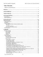
Page 6: ...38 Installation and Operation Table of Contents List of Figures and Tables Document PN 29010101 V2r0 5 Document History Revision Date By Description 1R0 November 2018 First Release 2R0 June 2019 Second Release ...

Page 7: ...Supply J1 Batt IN 40 Drive Box Power Supply 40 3Power Supply Extension 42 Input Output Connections J4 N2K000 J7 RFU 42 N2K Network J7 NMEA2000 42 Rotary Rudder Follower J4 RFU 43 Drive Outputs J2 Motor out J3 Drive Out 43 Reversing DC Motor Hydraulic Systems J2 Motor Out 43 Linear Actuators or Mechanical Rotary Drives J2 Motor Out J3 Drive Out 44 Shunt Field Reversing Motors J2 Motor Out J3 Drive ...

Page 8: ...Compass Setup 67 Sea Trials Procedures 68 Basic Operations 72 Main Menu Setup 74 Network Config Menu 78 Setup Procedures 82 NMEA 2000 Compass to System 84 Rotary Feedback 85 Standby Menu 86 Station Lock 87 Compass Source 88 Compass Cal Compass Calibration 88 Backlight Level 88 Fishzag Time 88 Battery 88 Power Steer Mode 89 Power Steer Menu 89 Stdby P Str Limits Power Steer Rudder Limits 90 Auto Na...

Page 9: ...ing 98 Correction set to XTE Cross Track Error Steering 99 Correction set to Both Steering To Along a Track 101 Refer to the Navigation System s manual for signal quality measurements and ideas on making improvements Alternate Navigation Display 103 Dodge 103 Advanced Operations 108 Advanced Operations 110 WORK Mode 110 Automatic WORK Mode 112 Manual WORK Mode 112 Work Menu 113 The states shown ar...

Page 10: ...Diagnostic LEDS 147 Appendix 5 148 Upgrading Firmware 148 Appendix 6 149 General Specification 149 Appendix 7 150 Compass Safe Distances 150 CE Compliance European Conformity 151 Warranty Information 152 User Notes and Settings 156 User Settings 158 Sitex SP38 Installation and Operation Table of Contents List of Figures and Tables Document PN 29010101 V2r0 9 ...

Page 11: ...nnections for Constant Running Electric Pump 45 Figure 20 Wiring Connections for A C Solenoids 46 Figure 21 External Alarm using SW D B Output 46 Figure 22 External Alarm using SW D B Output 47 Figure 23 External Alarm SW D B Output with Power Fail Option 47 Figure 24 External Alarm SW D B Output with Power Fail Option 48 Figure 25 Thruster Signals for SPU T 50 Figure 26 SP38 Control Head Rear Vie...

Page 12: ...ircle Turn Vessel Path 117 Figure 64 M O B Turn Query 118 Figure 65 M O B Turn Vessel Path 118 Figure 66 Fishzag Turn Query 119 Figure 67 Fishzag Turn 119 Figure 68 Turn Menu Screen 120 Figure 69 Station Lock Icons on the screen 121 Figure 70 NMEA 0183 NMEA 2000 system 128 Figure 71 GNSS G2 GPS Compass 129 Figure 72 Typical NMEA 0183 Connections 129 Figure 73 Fluxgate Compass 131 Figure 74 Wiring ...

Page 13: ...puts 49 Table 3 Turning Off SP38 System 54 Table 4 Vessel Type 62 Table 5 Nav Mode Correction 97 Table 6 NMEA 0183 Sentences Accepted by the SP38 141 Table 7 NMEA Sentence Priority 142 Table 8 Warning Messages 144 Table 9 Error Messages 145 Table 10 Critical Error Messages 146 Table 11 Diagnostic LEDs 147 Table 12 General Specifications 149 Table 13 Compass Safe Distances 150 Table 14 User Setting...

Page 14: ...Sitex SP38 Installation and Operation Document PN 29010101 V2r0 13 ...

Page 15: ...Sitex SP38 Installation and Operation Document PN 29010101 V2r0 14 Introduction ...

Page 16: ...Sitex SP38 Installation and Operation Document PN 29010101 V2r0 15 ...

Page 17: ...t your normal rate of steer If the boat is not turning as rapidly as you want for example with a cross or cross current holding back the bow you slightly increase the amount of rudder On the other hand if the boat is turning too fast you reduce the applied rudder a bit You then gradually reduce the applied rudder as the boat approaches the desired Heading You might even put the helm over opposite ...

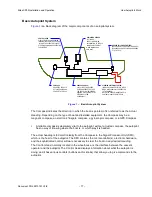
Page 18: ...S OPERATING PARAMETERS Figure 1 Basic Autopilot System The Compass indicates the direction in which the boat is pointed often referred to as the Actual Heading Depending on the type of boat and installed equipment the Compass may be a magnetic compass an electronic fluxgate compass a gyroscopic compass or a GPS Compass A reliable compass is absolutely vital to the autopilot without a trusted compa...

Page 19: ...u were steering manually Here s how it works The steering control algorithms running in the firmware on the SPU s microcomputer are constantly comparing multiple times per second the boat s actual Heading as indicated by the Compass to the desired Heading you have input If there is a difference the algorithms then calculate how much to move the rudder to bring the boat back onto the desired Headin...

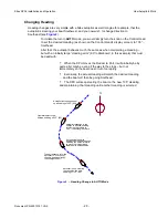
Page 20: ... is coming back too quickly the rudder will be moved quickly back to dead ahead or maybe even a bit to Port for a few seconds Eventually the actual Heading will match the desired Heading If and when the boat falls off course again the same sequence will be repeated In summary this is all very similar to steering the vessel manually it s just happening multiple times per second much more precisely ...

Page 21: ...rt it will probably be by quite a bit maybe even all the way to the stops but not immediately so the boat doesn t turn too rapidly Eventually the actual Heading will match the desired Heading and the boat will then be going Southeast The SPU will keep steering the boat on the new 135 Heading and maintaining that Heading until another Heading is selected Autopilot is steering vessel on a heading of...

Page 22: ...ex autopilots allow you to do just that with NAV mode The autopilot must be connected to an external source of navigation information commands and data such as a chart plotter or a Navigation program running on a PC A source of position data is also required it may be built into the external Navigation System or it may be another device or system like a GPS receiver such as a Sitex GPS Compass a L...

Page 23: ...the Navigation System updates the Cross Track Error This is why NAV mode is the answer to the track slip problem that can occur in AUTO mode when a cross current exists When a waypoint is reached the Navigation System sends the SPU the next set of navigation information for the next waypoint and the SPU then turns the boat to head to that next waypoint ...

Page 24: ...the autopilot s Control Head or any remote controls it is equipped with Steering when using the autopilot in this mode is done with two buttons and or a knob on the Control Head Button 1 and or a clockwise turn of the knob will move the rudder to Starboard causing the boat to turn that way the other button and or a counter clockwise turn of the knob will move the rudder to Port so that the boat tu...

Page 25: ...System Overview Sitex SP38 Installation and Operation Document PN 29010101 V2r0 24 System Overview ...

Page 26: ...Sitex SP38 Installation and Operation Document PN 29010101 V2r0 25 ...

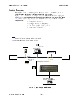
Page 27: ...Main Control Head The Signal Processor Unit SPU A Compass or other Heading Sensor The Rudder Feedback Unit NMEA2000 Terminator Female PN31810015 SP38 SPU PN20140002 20140006 SP38 Control Head TS38 Remote NMEA 2000 N2K Connection 6m drop cable Male Female PN31110052 NMEA2000 Terminator Male PN31810016 NMEA 2000 N2K Connection Trunk Backbone cable 12 24V Battery 12 24V Battery NMEA 2000 devices Comp...

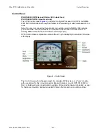
Page 28: ...2000 network you should make sure the CAN bus is terminated at the two ends of its back bone A working NMEA 2000 will have terminators installed properly SP38 Control Head incorporates a state of the art high visibility high resolution VGA colour LCD display Figure 4 Control Head The Control Head when shipped as part of a complete SP38 system is a core module with accessories for flush mounting op...

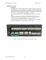
Page 29: ...utopilot s performance and will advise the user via the Control Head if any problems are encountered The most essential data for the SPU is the heading information and the rudder feedback signal The SPU can accept heading information from an NMEA 2000 device it can also accept heading information from an analog compass port or one of its 2 NMEA 0183 ports The SPU requires the rudder feedback signa...

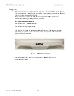
Page 30: ...pass Note It is always a wise and safe choice to have at least two compasses and or other Heading sensing devices on board G1 and G2 GNSS Compasses PN 11220016 G1 NMEA2000 model PN 11220018 G2 NMEA 2000 model The Sitex GPS Compasses are state of the art devices which can provide accurate 2D Heading and Position data to autopilots sonar chart plotters AIS transponders and otherNMEA2000 devices Figu...

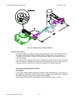
Page 31: ... ball is facing upwards Mount the Rudder Follower so that the Rudder Follower Arm is the same height as the Rudder Post Arm The Rudder Follower is centered when the arm is directly above the cable gland see Figure 8 The distance between the centerline of the Rudder Post and the Rudder Follower must not exceed 24 inches Make sure that the ball joints on the Rudder Arm and Rudder Follower arm are fa...

Page 32: ... length of cable supplied is too short to reach all the way to the SPU obtain a terminal strip and sufficient additional cable from your Sitex Dealer Mount the terminal strip in a convenient and dry location where it will not be subjected to moisture of any kind Heavy Duty Rotary Rudder Follower PN 20330012 A Heavy Duty Rotary Rudder Follower is available for special applications Check with your S...

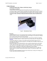
Page 33: ...Sitex SP38 Installation and Operation System Overview Document PN 29010101 V2r0 32 Figure 9 Heavy Duty Rotary Rudder Follower ...

Page 34: ... V2r0 33 Other Equipment Besides the optional equipment described above there is a wide choice of other equipment available for use with the SP38 Advanced Autopilot system see Appendices for Legacy product compatibility or contact your Sitex Dealer for information and details ...

Page 35: ...Sitex SP38 Installation and Operation Document PN 29010101 V2r0 34 Installation ...

Page 36: ...Sitex SP38 Installation and Operation Document PN 29010101 V2r0 35 ...

Page 37: ...protected against ground faults and safety hazards in accordance with local electrical codes THE AUTOPILOT IS INTENDED FOR SINGLE AUTOPILOT INSTALLATION ON THE NMEA2000 BUS NETWORK FOR REDUNDANT OR MULTIPLE SPU AND RFU DATA SOURCE INCLUDE OTHER INDUSTRY STANDARD AUTOPILOT MODULES CONNECTED TO THE NMEA2000 BUS NETWORK CONTACT Sitex FACTORY OR Sitex AUTHORIZED DEALER FOR SPECIFIC APPLICATION SOFTWAR...

Page 38: ...at you use stainless steel and or non corroding hardware to secure all equipment in the system Signal Processor Unit Mounting SPU The SPU should be mounted in a clean and dry area away from heat moisture and liquids of any kind The SPU should be centrally located and mounted far enough away from your vessel s compasses so as to minimize any possible electrical interference a good rule of thumb is ...

Page 39: ...rmance Refer to the table below If in doubt contact your Sitex Dealer for help Once the SPU is securely mounted you can begin wiring the various components of the system one at a time Function Use Type Gauge SPU Power Supply 2 X 12 AWG Steering Drive 12 24 VDC Solenoid Valve 3 X 18 AWG Steering Drive Reversing Motor 2 X 14 AWG refer to the instructions supplied with the Drive Motor Rudder Follower...

Page 40: ...eral turns using a small slotted screwdriver to open up the plug s wire clamp before a wire is inserted into that clamp the screw must then be turned clockwise until the wire is tightly held in the clamp All connectors and pins are labelled as shown in Figure 10 Installation Figures 10a SPU Plug Wiring Details Sitex SP Series SPU ...

Page 41: ... leg of a DC system will be red or white while wiring for the negative leg usually referred to as Ground will be black Power to supply the autopilot should be taken directly from a breaker or distribution panel The autopilot should be wired into its own individual breaker or fuse Using appropriately sized wire or cable see 3 22 Wire Gauge Requirements wire the battery connections to the connector ...

Page 42: ...Sitex SP38 Installation and Operation Document PN 29010101 V2r0 41 Figure 11 Typical Battery Connection to SPU Installation ...

Page 43: ... This minimizes any voltage drop between the breaker panel and the SPU Figure 12 Reducing Supply Voltage Losses Input Output Connections All NMEA 2000 Network connections from the SP38 Control Head SP38 SPU SP38 Remote NMEA 2000 devices are done through a standard Female or Male end NMEA 2000 drop Cable to the NMEA 2000 network Network J7 NMEA2000 Sitex Network is an NMEA 2000 port A 1m Pigtail fl...

Page 44: ...ug in connector as per the following diagram in Figure 14 Figure 14 Wiring Connections for Rudder Followers Drive Outputs The SP38 SPU is capable of directly driving a variety of steering systems Optional Drive Boxes are available for those systems not directly by the SP38 Contact your Sitex Dealer for more information Reversing DC Motor Hydraulic Systems J2 Motor Out Figure 15 Wiring Connections ...

Page 45: ... a solenoid activated clutch The clutch solenoid should also be activated by the SW D B output Refer to the following diagram in Figure 16 Figure 16 Wiring Connections for Linear Actuators or Mechanical Rotary Drives Shunt Field Reversing Motors J2 Motor Out J3 Drive Out For shunt field reversing motors connect the shunt field coil positive terminal to the SW D B output and the coil negative termi...

Page 46: ... thus providing an extra measure of safety WARNING Do Not wire an external JOG Lever directly to M1 M2 otherwise you may damage the drive output circuits in the SPU and void the warranty on your SP38 system and or the warranty of other equipment Figure 18 Wiring Connections for Standard Four Way Solenoid Valves NOTE The diagram in Figure 18 above assumes that an engine driven pump is used for the ...

Page 47: ... 20 Figure 20 Wiring Connections for AC solenoids External Alarm Output J2 Motor Out J3 Drive Out The Switched B or B may also be used for alarm output if you are not using it for drive purpose One of two outputs can be used for the external alarm Typically you would choose to connect the external alarm between Battery Positive PWR OUT and the Switched B SW D B outputs on J2 See the diagrams in Fi...

Page 48: ... device An Application Note is available which describes this potential problem in detail with suggested remedies The Note also lists a number of Piezo alarms which are known to work well with SP38 systems Please ask your Sitex Dealer or go to ComNav s web site for Application Note 2007 01 Power Failures J1 J2 J3 Some installations require separate monitoring for power failures This can be accompl...

Page 49: ...operating with the Hi or Lo speed steering parameters in effect in AUTO or NAV modes If the system is operating in WORK mode The status signals are meant to be used to allow indication of those conditions on an external alarm or indicator While both conditions are indicated on the Control Head s LCD display but it is also sometimes useful to have them alert with an external alarm or lamp at locati...

Page 50: ... All outputs are ESD protected but you still must use them with care Do not use more than about 0 5 m of cable to connect them to the external alarm indicator or stabilizer control circuit If you must connect to something farther away than that use a suitable buffer or isolator circuit a transistor a relay or preferred an opto isolator block With a relay be sure to wire a fly back suppressor diode...

Page 51: ...o full Port and vice versa that the RFU moves completely freely and is not being restricted in any way 6 Check the connections to the drive equipment from the SPU 7 Check that all cables are neatly routed and secured 8 Ensure that extraneous materials bits of insulation wire pieces or strands etc have been removed 9 If you have a magnetic sensor or a fluxgate compass check the connections on J9 10...

Page 52: ...lush mounting The flush mount is meant to be used when the Control Head is installed inside the boat If using the optional Deck Mount or commonly known Trunnion Mount bracket kit the unit is generally mounted on the console or in an overhead bulkhead location Complete instructions including drilling and cutting templates for each type of mounting are included with each kit Figure below shows the b...

Page 53: ...l heads and remote controllers communicate to the SPU through the NMEA 2000 bus When a station turns on it starts from the repeater status meaning it monitors all data from the SPU but cannot operate the SPU The user has to switch the Head to the command status before it can be used to control the SPU A Master station is the one that will automatically place itself to the command status after the ...

Page 54: ... verify your installation is complete 1 All power supply ports have been properly wired a SPU power port at J1 b SP38 Control Head at the 4 pin power connector c The NMEA 2000 network has proper power supply 2 The SPU installation is complete and the final check in section xxx has done 3 One Control Head is wired as the Master station 4 A Heading sensor exists in the NMEA 2000 network or a compass...

Page 55: ...wered down by removing the power supply turning off the circuit breaker or safety switch if installed recommended when fused This is also true for SP38 control Head and SP38 series of remote controllers The STANDBY ON OFF button on the SP38 Control Head is used to turn the system to a sleep mode where the display is turned off and minimum current is consumed STANDBY ON OFF Button Table 3 Turning o...

Page 56: ...the countdown and remain in STANDBY mode Turning on SP38 system from Sleep mode Press and hold the STANDBY ON OFF button on a SP38 will wake up the SP38 system All installed controllers for the same SPU restart as if they are powered on Using the Control Head LCD Screen and Buttons Figure 29 Using the Control Head Installation SP38 Autopilot 180503049 SPU P SPU 180702023 Waiting for IP SP38 0 1 Ju...

Page 57: ...BY ON OFF button To Turn On Press until the screen lights up Short Press STBY to enter Standby from a steering mode S appears on screen Press and hold for OFF screen will prompt with count down to OFF Double press for shortcut to USER CONFIGURATION in main SETUP menu 3 BRIGHTNESS button Long press toggles from Day to Night palette Short press brings up brightness level scale on screen Repeated sho...

Page 58: ...enu double press the Standby button Repeated presses on the TURN button will step through the other choices or selection items The selected turn is shown on the display To initiate the selected turn press the ARROW key corresponding to the desired turn direction See the Error Reference source not found section for more details on setting the default turn from the Special Turns available 10 STARBOA...

Page 59: ... For parameters with numbered values a clockwise turn of the knob will increase the value counter clockwise movements will decrease the value Non numerical values are generally arranged in a circular list for ease of use Note that every time a menu is accessed there is a little icon at the top of the display that looks like the COURSE CHANGE knob but with a line drawn through it This is a reminder...

Page 60: ... time power on The first time you power on your system SP38 SPU will also search for suitable data sources it needs in various operations from the NMEA 2000 network The following table shows what data are used for SPU Data Source Required in Operation modes Where to select change a source Heading All modes Network Config Rudder P Steer AUTO NAV Fixed from RFU port Navigation NAV Position AUTO ALC ...

Page 61: ...d after you wire the system you only power on one device for each data type This way the SPU will connect the same one If you want to use a non NMEA 2000 data source for example a fluxgate compass for heading you can change the input port for a particular source Refer to Table 2 SPU Available Input Ports Installation ...

Page 62: ...ing from turning off the system The following section describes each item in the Dockside Setup menu and how to use the menu to setup the devices directly connected to your SPU Note in the follow descriptions Move to means turning the knob to move the highlight line up down Select means pressing the Enter button when an item is highlighted SPU Reset A full reset of all the SP38 SPU s operating par...

Page 63: ...s for planning hull boats with outboards or stern drive legs Displ Full Displacement Choose this setting for full displacement boats that do not plane or rise out of the water at cruising speed Semi Semi Displacement Choose this if your boat rises partially out of the water at cruising speed Large Large with a slow Helm response Vessels in this category are typically over 125 LOA and or 100 GRT e ...

Page 64: ...ons chapter for full details Thrust Type SP38 SPU supports 4 options for the thruster used in used for the thruster assist function in the AUTO mode To use On Off or Proportional thruster with a CT7 box select On Off or Prop If you are Sleipner thrusters installed on your boat and you have a Sleipner S gateway in the network you can select S link SP38 SPU will use your Sleipner thrusters as an ass...

Page 65: ... can use those compass es Next compensate and calibrate all of your compasses Next do the initial settings of the various operating parameters Rudder Gain etc at high and low speed Finally test how well the autopilot performs in various sea conditions re adjusting parameters as needed NOTE The configuration will be transparent to the N2K network Selecting Vessel Type 1 Power the system up in the D...

Page 66: ...oard motor etc all are referred to here as rudders Some points to keep in mind while doing this procedure are Use the boat s manual steering system wheel tiller etc to move the rudder when prompted When moving the rudder to the maximum Port or Starboard position be sure to move it all the way to the physical stops NOTE in normal operation the autopilot always stops the rudder a few degrees away fr...

Page 67: ...ll movements the autopilot uses during normal operation After the autopilot has determined the time span for a Hard Over to Hard Over movement of the rudder there are several possible results If the HO HO time is fast the autopilot will have difficulty steering the vessel properly and you need to revisit the hydraulic setup If the HO HO time is too slow more than 22 seconds you will see a message ...

Page 68: ...of your analog compass fluxgate or magnetic When you have selected your compass type the autopilot will test the signals from the port and you will be prompted if the test has passed or not If you have a fluxgate compass the autopilot will promote you whether you want to calibrate it Do not calibrate it if you are tied to the dock You should calibrate your compass while you do sea trials NOTE duri...

Page 69: ...ore you begin Sea Trials it s a good idea to review how you steer your vessel manually and how that compares to how the SP38 performs when steering the boat under autopilot conditions Please re read the chapter on How Autopilots Work During Sea Trials you will test the default Steering Parameters of the SP38 on your specific vessel and make adjustments if necessary When the Steering Parameters are...

Page 70: ... 20 with the COURSE CHANGE knob Observe how the boat responds as it turns and settles into the new heading If the boat stops turning before the new heading is reached and then approaches it slowly either increase the Rudder Gain by 1 or decrease the Counter Rudder by 1 If the boat overshoots the new heading and then makes several turns back and forth across the new heading before settling down kno...

Page 71: ...e rate of turn is comfortable 5 Adjust the Lo speed Seastate setting to suit your preference Adjust Speed Trip Point 1 Bring up the Auto menu and set the Trip Point speed to something mid way between the speeds used for setting the Hi and Lo speed parameters in the steps discussed previously This should be a speed you will never travel at for any length of time for example in a planning hull boat ...

Page 72: ...t rougher you will probably need to increase the Rudder Gain 1 or 2 steps In very rough conditions you may want to reduce the Counter Rudder setting as well as increasing the Rudder Gain In quartering seas you may wish to increase Rudder Gain and the Seastate settings This will allow the boat to yaw a bit more as it comes off of the waves but typically the boat will come back onto course with mini...

Page 73: ...Sitex SP38 Installation and Operation Basic Operation Document PN 29010101 V2r0 72 Basic Operations ...

Page 74: ...Sitex SP38 Installation and Operation Document PN 29010101 V2r0 73 ...

Page 75: ...avLayout Psteer Layout Language System Info SPU info System Instance Device Instance LEVEL 1 LEVEL 2 LEVEL 3 Level 0 8 Day Night Mode Unit m km mil nm Unit m s km h mph kn Unit m km ft ftm UTC Local MM dd yyyy or dd MM yyyy 12HR or 24HR Auto 0 or 1 0 or 1 0 or 1 0 or 1 English Francais Espanol Isenska Italiano Norsk Deutsche Dansk Head Firmware Serial Number NetworkAddress Number SPU Fireware Seri...

Page 76: ... double press the CMD button for the MAIN Menu and then press the TURN KNOB button to select Backlight There are two modes DAY NIGHT that allow you to select for the most convenient and interference free viewing of the display Day The backlight level is adjustable between 5 to 100 Night The backlight level is adjustable between 2 to 20 Day Night Selects either the Day time screen or the Night time...

Page 77: ...s Depth Unit There are four Depth Unit choices m Meter Km Kilometer ft Feet ftm Fathom Time Reference To be defined Date Format To be defined Time Format UTC Universal Time and Local Local Time Mag Var Input To be defined Standby Layout There are 2 choices 0 or 1 Auto Layout There are 2 choices 0 or 1 Nav Layout There are 2 choices 0 or 1 P Steer Layout There are 2 choices 0 or 1 Language There ar...

Page 78: ...addr Network address eg 21 Manufacturer 404 for Sitex devices Model ID Sitex Product Model SP38 Autopilot S W Software Revision e g SP38 Head SPU Info This provides the following information for the SP38 SPU on a N2K network Network addr Network address eg 34 Manufacturer 404 for Sitex devices Model ID Sitex Product Model SP38 Autopilot S W Software Revision e g SP38 SPU D5 01 ...

Page 79: ...k The Network Config menu allow users to configure the preferred Compass Source Navigation Source multiple SP38 SPUs and multiple SP38 Heads that are involved with a SP38 Autopilot connecting to a NMEA 2000 Network To access the Network Config menu double press the CMD button to bring up the MAIN Menu and then press TURN KNOB to select User Data Group Allows the user to change the group data field...

Page 80: ...enu item will let you check all controllers and remotes that are current linked to the same SPU as this head AP Network sub menu AP Inst Group There are four Distance Units m Meter Km Kilometer second mil mile second nm nautical mile second Linked SPU Allows users to select one SPU from multiple SPUs on the NMEA 2000 network Please note that the screen will show all the devices on the NMEA 2000 Ne...

Page 81: ...or a backup in case of lost heading 9 Mag Var Source NOTE By default the SP38 Autopilot will select all of the above Data Sources automatically available on the NMEA 2000 network If there is more than one same Data Source PGN on the network the SP38 Autopilot will pick the first that is available If there is none available the SP38 Autopilot will do nothing It is up to the user to confirm they are...

Page 82: ...Menu Figure 38 Dockside Menu Enter from System Menu Set up the adjustable parameters for use in STANDBY User Config Power Steer P Steer AUTO NAV Work mode Turn modes which are stored in the SP38 SPU Please see the parameter descriptions under Basic Advanced Operation for proper adjustments ...

Page 83: ...e Battery 12 24V Battery 12 24V Battery GNSS Compass N2K Pigtail to Male Cable 1m PN61110063 2m Head Power Cable PN61110072 N2K T connector PN31810008 NMEA 2000 N2K Connection 6m cable Pigtail Male PN31110073 Sitex Rotary Rudder Follower PN20330008 Linkage PN20330007 NMEA2000 Power Supply The Sitex SP38 system is designed with safety messages for all situations requiring alerts and users must ackn...

Page 84: ...enu 5 Select Network Config 6 Select AP Network 7 Press Enter TURN KNOB button to acknowledge the Warning Message press ENTER to dismiss 8 Select Linked SPU 9 Select the SPU serial number 10 Press Enter to select the SPU Now the Control Head and the SPU are connected together and the Remote is in control 11 Press the CMD button to go back to the previous screen 12 Press and hold the CMD to take co...

Page 85: ...ress Enter brought up by clicking single press the TURN knob to acknowledge the alarm message 2 Press and hold the CMD button to take control The NO COMMAND HEAD and Compass Error messages will disappear NMEA 2000 Compass to system As explained in First time power up in 4 1 4 System Setup the autopilot will automatically link to a compass in the network If for any reason the system does not link t...

Page 86: ...take control of the Head 12 From the STANDBY mode screen the compass reading should show HDG XXX X T where XXX X is the True Heading from N2K network Rotary Feedback To configure Rotary Follower unit to system 1 Enter SPU DOCKSIDE Menu power down up the system press LEFT RIGHT ARROW KEYS at the same time when the instruction is on the screen 2 Note that the D Dockside Setup Menu on the left side o...

Page 87: ...010101 V2r0 86 Standby Menu The Standby menu consists of a number of items that have a general bearing on how the autopilot operates To access the Standby menu double press the red STANDBY ON OFF button To get the full menu it must be Standby mode Figure 40 Standby Menu ...

Page 88: ...nd the others are simply repeater stations You can take command with any of the repeater stations by simultaneously pressing the PORT and STARBOARD ARROW buttons on the repeater However to prevent an unauthorized person from doing this the main Control Head can lock out all of the others Station Lock must be changed to Unlock before the repeater stations can take command For more detail refer to S...

Page 89: ... NAV button Position Table 2 SPU Available Input Ports Compass Cal Compass Calibration This feature allows you to synchronize the compass on the autopilot with an external source Simply turn the COURSE CHANGE knob until the Compass Cal value reads the same as your reference source NOTE For safety reasons Compass Cal may not be adjusted in AUTO or NAV modes so it does not appear if the Standby menu...

Page 90: ...e physical rudder limits You can limit the maximum amount of rudder travel in POWER STEER mode by turning on the Power Steer limits Turning on these limits and adjusting them to suit is done in the Power Steer menu The COURSE CHANGE knob can also be used to move the rudder in POWER STEER mode Each click of the knob will move the rudder a finite yet equal amount Figure 41 Typical Power Steer Mode S...

Page 91: ...t to hard over starboard so that the autopilot can measure these positions These mechanical hard over positions are known as the physical limits beyond which the rudder simply cannot be turned However you can artificially limit the rudder travel through the autopilot software To do so set the Power Steer Limits to the number of degrees port and starboard that you would like to limit the rudder mov...

Page 92: ... was on at the moment the mode was entered as the initial Commanded Heading To change the Commanded Heading use the COURSE CHANGE knob A clockwise turn will result in an increase of the Heading A counter clockwise turn will decrease the Heading One click will change the Heading by 1 degree A quick spin of the knob changes the Heading by 10 degrees The autopilot will then bring the boat around to t...

Page 93: ...urse Alarm that will be activated should the boat fall off the Commanded Heading by more than 20 There is a 30 second delay on this alarm Auto Menu displayed by double press the red Auto button LEVEL 1 LEVEL 2 LEVEL 3 Rudder Gain Counter Rudder Seastate Turn Rate Limit Parameter Set Seed Trip Point Speed Source ALC TrimStart Pos Gain 1 10 Gain 1 10 Auto 1 10 0 1 10 Auto Hi Low Speed Trip Point N20...

Page 94: ...wise until the value reads A There are two Seastate settings one is for low speed operations LO and one is for high speed operations HI Turn Rate Varying the Turn Rate parameter controls the maximum rate at which the vessel may make a course change in AUTO or NAV modes return to its original heading after a dodge manoeuvre or execute a Special Turn Factors such as speed load hull characteristics a...

Page 95: ...rce and or the Navigation data source ALC Automatic Leeway Correction The SP38 s Automatic Leeway Correction ALC feature is turned on or off with this parameter It is active only in AUTO mode See the Following a Track section for more information Thruster Assist or Thruster Gain If the Thrust Type in the Dockside menu is not None these two functions will be available in the menu Thruster Assist se...

Page 96: ...k See the 5 6 Dodge and Jog Lever Turns sections for more information You can limit the maximum amount of rudder travel in NAV mode by turning on the Auto Nav rudder limits Turning them on and adjusting them to suit is done in the Power Steer menu The SP38 has an automatic Off Course Alarm that will be activated should the vessel fall off the commanded course in NAV mode by more than 20 There is a...

Page 97: ...t that input when in NAV mode to obtain the bearing and course to steer information The selected input can be the same one used for the Compass source and or the Speed source XTE Limit Cross Track Error Limit The autopilot will raise an alarm while in NAV mode if the vessel s cross track error exceeds the limit set here WayPt Arrival Waypoint Arrival When the vessel arrives at a waypoint or the en...

Page 98: ...rom its current heading so as to minimize Cross Track Error No Course To Steer information from the Navigation System is used Both Course To Steer plus Cross Track Error The autopilot steers a modified course taken from the Navigation System s Course To Steer The amount of modification is proportional to the amount of Cross Track Error This method is generally best for normal usage Table 5 NAV Mod...

Page 99: ...d waypoint Setting Max Correction to something less than 90 can minimize this phenomenon yet will get you back on track less quickly Commanded Heading Displayed The commanded heading shown on the display in NAV mode may not be the same as the bearing given by the Navigation System This is because there are three different methods that the SP38 can use to process and react to the navigation data fr...

Page 100: ... and manually steer the vessel away from the waypoint track by a few hundred meters or more 4 Place the SP38 into NAV mode by pressing and holding the NAV button until the unit beeps and the letter N appears in the upper left portion of the display 5 Observe the commanded heading on the SP38 display It should match the bearing reported by the Navigation System Caution Be sure to maintain a sharp l...

Page 101: ... so as to be familiar with it by performing the following steps 1 Change Correction in the Nav menu to XTE 2 Make sure the Navigation System is turned on and that a waypoint is programmed in 3 Switch the autopilot to STANDBY mode and manually steer the vessel onto the track 4 Place the SP38 into NAV mode by pressing and holding the NAV button until the unit beeps and the letter N appears in the up...

Page 102: ...he total number of degrees that the autopilot will correct the heading received from the Navigation System as it tries to bring the vessel back on track is limited to the value set for XTE Limit in the Nav menu Caution Be sure to maintain a sharp lookout to ensure that there are no obstacles between the vessel and the original track Correction set to Both Steering To Along a Track In this method s...

Page 103: ...rogrammed in Usually this means selecting a waypoint from a list and pressing the GOTO button 2 Steer the boat close to the waypoint track 3 Put the SP38 in NAV mode by pressing and holding the NAV button until the unit beeps and the letter N appears in the upper left portion of the display 4 Observe the vessel s response for several minutes if the vessel seems to be continually falling off course...

Page 104: ...mall numbers in the lower corners of the highway display These indicate the scale of the display There are four scales that can be shown on the highway display 0 2 0 5 1 5 and 3 0 nautical miles The scale changes automatically to give the best resolution When in AUTO NAV WORK or modes you can use the PORT and or STARBOARD ARROW buttons to avoid dodge around an obstacle in the water Pressing and ma...

Page 105: ...egin to turn the vessel back to the Commanded Course but this time the turn will occur at no greater than the maximum turn rate that is set in the Steering Parameters NOTE If you dodge the vessel in AUTO or WORK modes when you release the PORT or STARBOARD ARROW button the vessel will return to the same Heading but not the same Track The new Track will be offset from the original Track by the dist...

Page 106: ... the vessel s rudder speed and steering response time and any directional offset that the vessel exhibits when the rudder is centred Releasing one button will re start a Dodge in the other direction Releasing both buttons will end the dodge completely with the same mode dependant behaviour with respect to Resuming the Track as noted previously Jog Lever Turns Figure 56 Typical Jog Lever Activated ...

Page 107: ...l limits of rudder travel When you release the Jog Lever the autopilot will return the vessel to the current commanded Heading if in AUTO or WORK modes or to the current track to the next waypoint if in NAV mode Whenever a Jog Lever is activated a large J is displayed in the upper left corner of the Control Head s screen see Figure 56 temporarily replacing the current mode s indicator letter The j...

Page 108: ...Sitex SP38 Installation and Operation Document PN 29010101 V2r0 107 ...

Page 109: ...Sitex SP38 Installation and Operation Document PN 29010101 V2r0 108 Advanced Operations ...

Page 110: ...Sitex SP38 Installation and Operation Document PN 29010101 V2r0 109 ...

Page 111: ...off the Commanded Heading by more than 20 There is a 30 second delay on this alarm Automatic WORK Mode Although WORK mode can be used manually it works best if a valid NMEA source for the boat s speed is also interfaced to the autopilot The speed source must also be properly configured in the Auto menu see page 127 With a valid NMEA speed source WORK mode can be engaged automatically when the boat...

Page 112: ... on the Work menu Other effects take place in WORK mode too The corrective rudder movement calculated for Counter Rudder is reduced to the minimum possible for the vessel type i e as if the Counter Rudder parameter was set to 0 which enhances the effect of the Rudder Gain and Rudder Scale Factor Turn Rate is limited to 10 per second while WORK is active for all changes of Heading controlled by the...

Page 113: ...letter W appears beside it Then double press the WORK button to bring up the Work menu Highlight Work Mode State Then use the COURSE CHANGE knob to change the selection to M_On Manual On WORK mode is now engaged Caution When Manual WORK mode is engaged large rudder movements may occur If your boat is traveling too fast these rudder movements may affect the stability of the boat Do not engage Manua...

Page 114: ...udder Bias This menu line only appears when WORK mode is active It shows the current rudder bias which can be adjusted if desired Autotrim The autopilot s WORK mode can be configured to use manual or automatic rudder bias trim when in WORK mode the default is to use automatic bias Manual rudder bias is fixed by the position of the rudder when the autopilot first enters WORK mode but can be adjuste...

Page 115: ...ror detected for example the error times the Rudder Gain and using some constants which depend on vessel type but in WORK mode that amount will also be multiplied by the Scale Factor This will always result in larger rudder movements for a given course error Work Mode State This parameter shows the current status of WORK mode It is also a means to force WORK mode to be active or not Normally WORK ...

Page 116: ...uery for a direction 2 If a different special turn other than the default shown is desired press the TURN button again The next special turn in the available list will be shown Press the TURN button again and again until the desired special turn is shown 3 Press either the PORT or STARBOARD ARROW button to select the direction in which to execute the Special Turn Figure 59 Typical Special Turn Que...

Page 117: ...101 V2r0 116 U Turn For a U Turn the autopilot calculates a reciprocal course to the vessel s heading and then turns the vessel to that heading in the appropriate direction once the PORT or STARBOARD ARROW button is pressed Figure 60 U Turn Query Figure 61 U Turn Vessel Path ...

Page 118: ...urn the autopilot steers a never ending circle in the appropriate direction once the PORT or STARBOARD ARROW button is pressed The Turn Rate setting in the Auto menu governs the rate of turn To stop the circle press the TURN button again or switch modes Figure 62 Circle Turn Query Figure 63 Circle Turn Vessel Path ...

Page 119: ...own as an Emergency or E turn This will bring the vessel onto a reciprocal heading typically right down the vessel s own wake The PORT or STARBOARD ARROW buttons are used to determine the initial turning direction For best accuracy do not adjust the vessel speed once this turn has been initiated Figure 64 Man Overboard MOB Turn Query Figure 65 Man Overboard MOB Turn Vessel Path ...

Page 120: ... in the direction specified when you pressed the PORT or STARBOARD ARROW button After 30 seconds the autopilot will return to the original course and start the timer over again This time when the timer goes off the autopilot will make a 60 course change in the opposite direction Again after 30 seconds the autopilot will return to the original course where the cycle repeats itself The Fishzag turn ...

Page 121: ...n Off U Turn M O B Fishzag Pretack Circle 5 90 30 300 Turn screen Special Turn Select Off to disable the TURN button No Turn described in this menu is allowed when Speical Turn is Off Default Turn Select different Turn such as U Turn Circle Turn M O B Pretack Fishzag Pre Tack Angle Pre Tack Angle allows users to set the degrees of course change to make during the Pre Tack turn This angle can be se...

Page 122: ...tation lock is for the main Control Head or an Auxiliary Figure 69 Station Lock Icons on the screen The controller In command shows a locked locker icon The Locker signifies that all stations except for the Master Control Head and the controller which is currently In command are locked out Controllers that are Repeaters cannot take command Caution If your SP38 system is equipped with Jog Levers yo...

Page 123: ...Sitex SP38 Installation and Operation Document PN 29010101 V2r0 122 Care and Maintenance ...

Page 124: ...Sitex SP38 Installation and Operation Document PN 29010101 V2r0 123 ...

Page 125: ...T BE AVOIDED Exposure to prolonged direct sunlight should be avoided in order to prevent damage to the electronics and housing and UV induced fading of the LCD Protection of Wires and Cabling After installation ensure that the system components are securely mounted and will not shake loose due to the vibrations that can be expected in a marine vessel Ensure that the cabling and wiring to all syste...

Page 126: ...emoved To do so gently pry up the center portion of the plastic rivets which fasten the cover to the SPU s case be careful not to lose any of the plastic pieces After the fuse s are replaced the cover must be re installed and remain in place during normal operation Designator Sitex Part Number Generic Description Manufacturer s and Part Number s F1 60810009 20A Non Time Delay 125V x 1 1 4 Bussman ...

Page 127: ...Sitex SP38 Installation and Operation Document PN 29010101 V2r0 126 Appendices ...

Page 128: ...Sitex SP38 Installation and Operation Document PN 29010101 V2r0 127 ...

Page 129: ...ttery 12 24V Battery 12 24V Battery N2K Pigtail to Male Cable 1m PN61110063 2m Head Power Cable PN61110072 N2K T connector PN31810008 NMEA 2000 N2K Connection 6m cable Pigtail Male PN31110073 Sitex Rotary Rudder Follower PN20330008 Linkage PN20330007 Fluxgate Compass Magnetic Compas OR NMEA2000 Power Supply Figure 70 NMEA 0183 NMEA 2000 System Appendix 1 NON NMEA 2000 Heading Sources The following...

Page 130: ...n 3 00 Many marine electronics devices such as digital compasses GPS receivers chart plotters and electronic charting systems to name a few have outputs complying with NMEA 0183 Two such devices can be connected directly to the SP38 s SPU by wiring them into the plug mated to the receptacle labelled J6 NAV I O The signals are utilized by configuring NAV1 NAV2 through DOCKSIDE Setup select NMEA und...

Page 131: ...1 stop bit Correct NMEA sentence structure Checksums are optional but must be valid if present It may also be possible to use RS 232 electrical levels in some cases such as when using a PC NOTE The NAV2 port can optionally be run at 9600 Baud To do so you simply need to set the other device to transmit at that rate The SPU automatically sets the rate for this port by looking for valid NMEA data at...

Page 132: ...tre 40 cable with flying leads to wire it into the SP38 s SPU Figure 73 Fluxgate Compass Compass Wiring All compasses other than NMEA 0183 compasses are connected to the SPU receptacle labelled J9 COMPASS see the Compass section for how to connect NMEA compasses If you ordered your SP38 system with a Sitex Fluxgate Compass the cable wires connect to the J9 receptacle as per the diagram in Figure 7...

Page 133: ...n up the system press LEFT RIGHT ARROW KEYS at the same time when the instruction is on the screen 2 Note that the D Dockside Setup Menu on the left side of the screen 3 For first time compass set8 up it is not important to have a valid compass reading it may be from N2K network Compass Reading HDG XXX is a N2K compass 4 Note that D Dockside Setup Menu on the left side of the screen 5 Select Compa...

Page 134: ...ding it ay e from N2K network Compass Reading HDG XXX is a N2K compass 4 Note that D Dockside Setup Menu on the left side of the screen 5 Select Compass Setup 6 Select Analog Compass from none to Mag 7 It will display Magnetic sensor found 8 After Dockside the screen returns to Compass 9 Select Exit on the Dockside Setup Menu DO NOT use the MENU button to go to the previous screen 10 Check that S ...

Page 135: ...Advanced Autopilot System The CR 203 Remote provides selection of STANDBY TILLER AUTO and NAV mode In TILLER mode the vessel s rudder position is tied to the position of the CR 203 s Tiller knob In STANDBY AUTO NAV modes the CR 203 operates identically to the Commander P2 s Control Head The CR 203 Remote supports WORK mode Refer to WORK Mode in the Advanced Operations section for an explanation of...

Page 136: ...ote PN 20310025 The TS 203 Fixed Remote is a heavy duty Full Follow Up FFU Lever control which allows the operator to control the tiller steering and autopilot functions from any work station flying bridge or remote location on the vessel Figure 77 TS 203 Fixed Remote Appendices ...

Page 137: ...r TS203 wire them into the plug mated to the receptacle labelled J10 Control Head as the following diagram Control Head Connection Figure 78 Wiring Connections for Control Head Handheld Remotes and Fixed Remotes PLUG INTO J10 Control Head PLUG INTO J10 Control Head Remote CR203 TS 203 Cable Connection Appendices ...

Page 138: ... designed for marine use The spring centered lever is moved port or starboard as desired to provide non follow up time dependent electrical control of the vessel s steering system Jog Levers Figure 79 Jog Lever Any number of Non Follow Up NFU Jog Levers can be connected to the SP38 SPU They are simply wired in parallel to each other Connect them to the terminal labelled J5 JOG LEVER as per the fol...

Page 139: ...nner the autopilot must be turned on The autopilot will then move the rudder either port or starboard for as long as the Jog Lever is held activated However the autopilot will stop the rudder when it gets to the user adjustable rudder limits programmed into the autopilot This reduces stress on the steering system Appendices ...

Page 140: ...tional Bezel Kit Part 30360004 Wheelhouse Case PN 20360017 and Watertight Case PN 20360016 are available Figure 81 External Rudder Angle Indicator 3 Model Rudder Angle Indicators The SP38 system will drive up to five 500 microampere Rudder Angle Indicator RAI meters such as those supplied by Sitex PN 20360014 Mounting instructions are included with each meter Wire the meter to the plug for the SPU...

Page 141: ...PGN numbers Accepted and Transmitted by the Autopilot Transmitting standard PGNS 59392 59904 60928 126996 126464 126208 127250 127245 127237 128259 129025 129026 129283 129284 126993 Receiving standard PGNs 60928 59904 59392 126208 127250 128259 129025 129026 129029 129283 129284 Appendices ...

Page 142: ...um Specific GNSS Data Speed Magnetic Variation VBW Dual Ground Water Speed Speed VHW Water Speed and Heading Speed VTG Course Over Ground and Speed Speed XTE Cross Track Error Cross Track Error Table 6 NMEA 0183 Sentences Accepted by the SP38 All sentences received must have valid checksums Sentences which do not have any checksums or have invalid checksums will be ignored In some cases if the mis...

Page 143: ... origin to destination magnetic or true Waypoint ID Bearing present to destination magnetic or true Course to steer magnetic or true APB 13 Vessel speed RMA 14 Vessel speed Magnetic variation RMC 15 Latitude and longitude GLL 16 Table 7 NMEA Sentence Priority NOTE The Heading value used by the SP38 may be in Degrees Magnetic or True depending on which sentences are received assuming all sentences ...

Page 144: ...Identifier is AP in all cases All messages have valid checksums The PCMS sentence is output once per second if the Vessel Type in the Dockside Setup menu is set to Sail Example PCMNS PS 340 0 339 6 M 0 1 0 4 2C 1 the symbol that starts all NMEA 0183 sentences 2 P identifies a proprietary sentence 3 CMN the identifier assigned to Sitex Marine Ltd by NMEA 4 S status type sentence 5 Mode SB STANDBY m...

Page 145: ...re than 20 different than the commanded angle for more than 30 seconds Adjust steering parameters to prevent this EEPROM ERROR The system has detected a non fatal error in one of the memory devices on the SPU Contact your Sitex Dealer for repair service at your earliest convenience NO AUX 1 The system previously detected an auxiliary connected to J10 but cannot detect it now Check all wiring TURN ...

Page 146: ...LID SPEED DATA Valid NMEA 0183 Speed data has not been received at NAV1 or NAV2 for 28 seconds Check that the Navigation System sending the data is turned on and functioning properly Check the wiring between the system and the SPU INVALID HEADING If an Analog Compass is selected as the Compass Source in the Standby menu this message indicates that the signals from the compass are faulty Check the ...

Page 147: ... type only LOW BATTERY The SP38 has detected that the battery supply voltage is less than 10 VDC which is too low to continue safe operation Check all wiring as well as the battery batteries ROM ERROR The SP38 has detected a problem in its program memory Return the unit to your Sitex Dealer for repair RFU NOT FOUND The SP38 cannot detect the presence of a Rudder Follower Unit Check all RFU wiring ...

Page 148: ...D will be shut off whenever the motor is activated in one direction which direction depends on how the reversing motor was plumbed in and wired M2 STBD For systems that utilize Solenoid steering valves this LED will be lit whenever the solenoid is activated For Reversing Motor systems this LED will be shut off whenever the motor is activated in the opposite direction to the M1 output NMEA 0183 IN ...

Page 149: ...to an existing system installation in the field by a Sitex Dealer or even by the vessel operator For the SP38 system this is done with a Firmware The Firmware link is available from your authorised dealer The Link will provide intuitive instructions on how to download latest firmware to install the Upgrade Contact your Sitex Dealer for more information Caution Be sure to read all of the documentat...

Page 150: ...nsumption SPU 400 mADC Control Head 350 mADC Drive Output 20 Amps max Navigational Interface NMEA 2000 compliant Network NAV1 input NMEA 0183 compliant optically isolated 4800 Baud NAV2 input NMEA 0183 compliant optically isolated auto baud detecting 4800 9600 19 2K and 38 4K Baud NMEA 0183 output Heading 10x per second and Autopilot status 1x per second NMEA 0183 compliant RS 422 compliant RS 485...

Page 151: ...gency compasses Sitex PN Description Standard Compass Limit 5 4 H Steering Compass Limit 18 H 20140005 Signal Processing Unit SPU 28 cm 16 5 cm 30140008 Control Head 32 cm 21 cm 20310035 TS38 Tiller steering Remote 31 cm 18 cm 20310036 NF38 Jog Lever 13 cm 8 cm 20330008 Medium Duty Rotary Rudder Follower 20 cm 8 cm 20330012 Heavy Duty Rotary Rudder Follower 62 cm 40 cm H horizontal flux density in...

Page 152: ...C945 EN60945 Marine Navigation Equipment General Requirements Applicable sections for methods of testing and required test results are Section 4 5 4 Radiated Interference Section 4 5 4 Immunity to Electro Magnetic Environment Annex A Section A 3 Immunity to Conducted Audio Frequencies Annex A Section A 4 Immunity to Earth Lead Coupling Annex A Section A 6 Immunity to Radiated Interference Test res...

Page 153: ...red or mutilated SI TEX Marine Electronics assumes no responsibility for damage incurred during installation This Limited Warranty is effective only with respect to the original purchaser Any cost associated with transducer replacement other than the cost of the transducer itself is specifically excluded from the Limited Warranty Travel cost incurred will not be accepted by SI TEX Marine Electroni...

Page 154: ...NY 11901 631 996 2690 HOW TO OBTAIN SERVICE UNDER THIS WARRANTY To provide greater flexibility SI TEX Marine Electronics gives you the option to obtain service under the warranty by either a Contacting an authorized SI TEX Marine Electronics service station The closest service station may be found by contacting your dealer of purchase OR b Shipping your equipment prepaid via UPS FED EX or truck wi...

Page 155: ...stomer Service The contract numbers and e mail address for Sitex Customer Service are Sitex Main Office 1 631 996 2690 Sitex Fax 1 631 996 2693 Sitex Customer Support E mail address customerservice si tex com Sitex Website www si tex com Sitex Main Office Address SI TEX Marine Electronics 25 Enterprise Zone Drive Ste 2 Riverhead NY 11901 Technical Support is available from 9 00 AM to 5 00 PM Easte...

Page 156: ...Sitex SP38 Installation and Operation Document PN 29010101 V2r0 155 Warranty ...

Page 157: ...Sitex SP38 Installation and Operation Document PN 29010101 V2r0 156 User Notes and Settings ...

Page 158: ...Sitex SP38 Installation and Operation Document PN 29010101 V2r0 157 ...

Page 159: ...ixed Float None Compass setup press ENTER Knob button to do n a Drive setup press ENTER Knob to do n a Exit press Enter Knob to do n a Alarm O P None SW D B SW D B None External Alarm Type All Watch All Thrust Type CT7 None On Off Prop None Thrust MIN CT7 0 70 0 Thrust MAX CT7 Thrust min to 100 0 Language English Français Español Íslenska Italiano Norsk Deutsche Dansk Standby Menu Station Lock Loc...

Page 160: ...ffset 0 15 0 Auto Menu Rudder Gain 1 10 8 5 Counter Rudder 0 10 3 3 Seastate Auto 1 10 A A Turn Rate 0 1 20 8 5 Parameter Set Lo Hi Auto Auto Speed Trip Pt 1 20 10 Speed Source NAV1 NAV2 NAV1 ALC On Off Off Thruster Assist only if Thrust Type is not None Off or 1 7 in 0 5 steps Off Thruster Gain only if Thrust Type is not None Low Med High Low Nav Menu Nav Source NAV1 NAV2 N2K NAV1 XTE Limit 0 01 ...

Page 161: ...01 V2r0 160 Parameter Range Default Value User Settings 1 User Settings 2 Work Menu Rudder Bias Auto Nav rudder limit or physical limit Set at Runtime Autotrim Off On Off Work Trip Pt 1 10 2 Rudder Scale 0 25 3 00 step 0 25 1 00 Work Mode State A_Rdy A_On M_Rdy M_On Set at Runtime ...

Page 162: ...Sitex SP38 Installation and Operation User Notes and Settings Document PN 29010101 V2r0 161 User Notes ...

Reviews: