Sitex SP38 Installation and Operation
System Overview
Document PN
29010101
V2r0
-
30
-
Rudder Followers
Standard Rotary Rudder Follower and Rudder Linkage
PN 20330008 and 20330007
The
Sitex
SP38
is normally supplied with a
Sitex
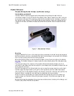
Medium Duty Rotary Rudder Follower.
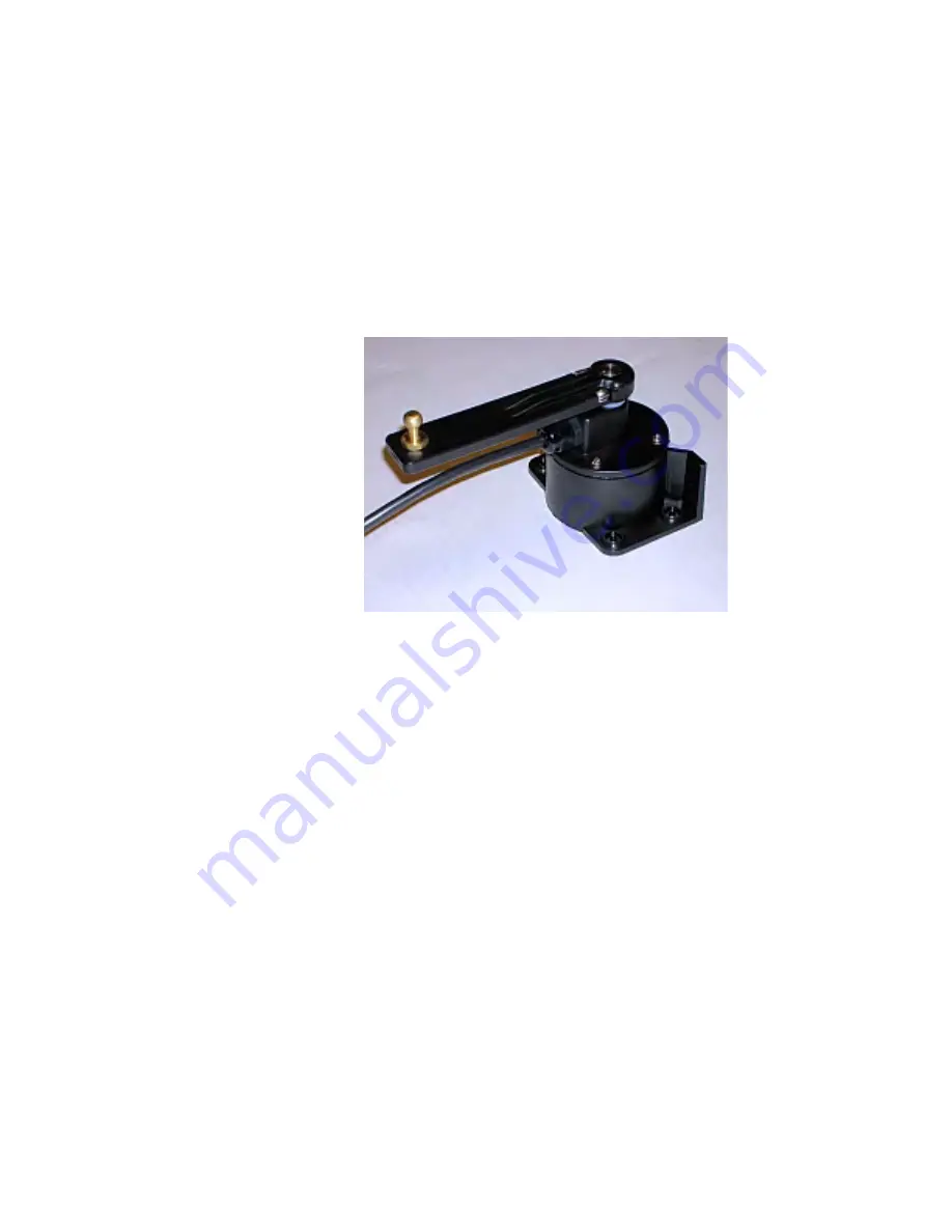
The Rudder Follower is used to transmit the position of the vessel’s rudder to the SPU. It should
be connected to the part of the steering system that the autopilot controls. Normally, it would be
the vessel’s rudder. However, if the vessel has two-stage steering, where the autopilot drives a
control or servo ram, the Rudder Follower should be mounted to the servo ram rather than the
rudder.
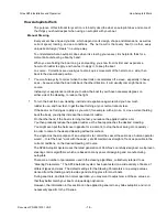
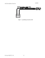
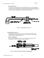
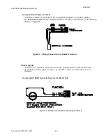
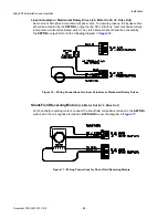
Figure 7 – Rotary Rudder Follower
Mounting
Install the Rudder Post Arm on the rudder post using a stainless-steel band clamp (not supplied).
Bolt the ball joint to the hole in the Rudder Post Arm corresponding to the diameter of the Rudder
Post in inches, making sure the ball is facing upwards.
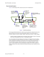
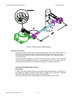
Mount the Rudder Follower so that the Rudder Follower Arm is the same height as the Rudder
Post Arm. The Rudder Follower is centered when the arm is directly above the cable gland (see
Figure 8
).
The distance between the centerline of the Rudder Post and the Rudder Follower must not
exceed 24 inches. Make sure that the ball joints on the Rudder Arm and Rudder Follower arm are
facing upwards as shown.
Snap the rod assembly onto the ball joints. Be sure to close the release clamps on each socket,
and then adjust the length of the rod to get the correct geometry with the rudder dead-ahead.
If the locking screw in the Rudder Follower arm has been loosened, or the arm removed from the
Rudder Follower, re-attach the arm and check the potentiometer center position.
When the rudder is dead-ahead, the electrical resistance between the wires of the black and
green wire pair, and the wires of the white and green wire pair, should be equal (approx. 600
ohms each).
Be careful to check the installation for any mechanical obstructions or binding of the linkage, and
correct it now, before it becomes a problem.
Summary of Contents for SP38 Autopilot
Page 2: ......
Page 14: ...Sitex SP38 Installation and Operation Document PN 29010101 V2r0 13 ...
Page 15: ...Sitex SP38 Installation and Operation Document PN 29010101 V2r0 14 Introduction ...
Page 16: ...Sitex SP38 Installation and Operation Document PN 29010101 V2r0 15 ...
Page 26: ...Sitex SP38 Installation and Operation Document PN 29010101 V2r0 25 ...
Page 35: ...Sitex SP38 Installation and Operation Document PN 29010101 V2r0 34 Installation ...
Page 36: ...Sitex SP38 Installation and Operation Document PN 29010101 V2r0 35 ...
Page 74: ...Sitex SP38 Installation and Operation Document PN 29010101 V2r0 73 ...
Page 108: ...Sitex SP38 Installation and Operation Document PN 29010101 V2r0 107 ...
Page 109: ...Sitex SP38 Installation and Operation Document PN 29010101 V2r0 108 Advanced Operations ...
Page 110: ...Sitex SP38 Installation and Operation Document PN 29010101 V2r0 109 ...
Page 123: ...Sitex SP38 Installation and Operation Document PN 29010101 V2r0 122 Care and Maintenance ...
Page 124: ...Sitex SP38 Installation and Operation Document PN 29010101 V2r0 123 ...
Page 127: ...Sitex SP38 Installation and Operation Document PN 29010101 V2r0 126 Appendices ...
Page 128: ...Sitex SP38 Installation and Operation Document PN 29010101 V2r0 127 ...
Page 156: ...Sitex SP38 Installation and Operation Document PN 29010101 V2r0 155 Warranty ...
Page 157: ...Sitex SP38 Installation and Operation Document PN 29010101 V2r0 156 User Notes and Settings ...
Page 158: ...Sitex SP38 Installation and Operation Document PN 29010101 V2r0 157 ...

