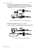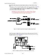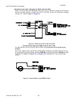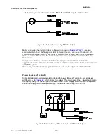
Sitex SP38 Installation and Operation
Document PN
29010101
V2r0
- 3
8
-
Compass Safe Distances
section for specific values, if you do not have that much space.
The SPU can be mounted vertically on a bulkhead or horizontally on a deck or shelf.
•
If mounted vertically, it should be positioned so that all wires and cables will exit from
the bottom of the SPU (after running sideways, left and/or right as appropriate, from the
SPU connectors under the SPU’s wiring cover)and secured to avoid accidental
disconnection from the receptacle using tie wraps or other appropriate securing
hardware.
•
If mounted horizontally, all wires and cables should have a drip-loop formed in them.
Each SPU is shipped from the factory with a package of four (4) mounting feet and separate
instruction sheet that includes dimensions for drilling holes to fasten the feet to the vessel.
Wire Gauge, SPU
Due to the relatively high current requirements of an autopilot compared to many other types of
electronic equipment, Using the correct size of wire to connect the various components is very
important. Undersized wiring will result in power losses which can affect overall efficiency and
performance. Refer to the table below. If in doubt, contact your
Sitex
Dealer for help.
Once the SPU is securely mounted, you can begin wiring the various components of the
system, one at a time.
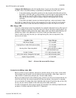
Function / Use
Type / Gauge
SPU Power Supply
2 X 12 AWG
Steering Drive: 12/24 VDC Solenoid Valve
3 X 18 AWG
Steering Drive: Reversing Motor
2 X 14 AWG
(refer to the instructions supplied
with the Drive Motor)
Rudder Follower
3 X 18 AWG Shielded cable
GPS, Chart-plotter, Navigation Computer
2 X 24 AWG Shielded cable
Rudder Angle Indicator
2 X 24 AWG
Table 1 – Minimum Recommended Wire Gauges
Connectors & Wiring Label, SPU
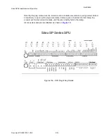
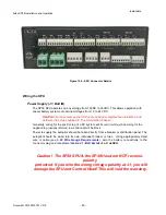
Each connector is a pin receptacle, with the pins sized according to how much current will be
carried (bigger pins for higher current). Each pin has a signal name, rather than a number, to
make it easier to match wires with pins (see connector label, below).
Each pin receptacle mates with a matching plug, which in turn has screw-clamp terminals, into
which the wires from the external equipment and devices (battery, drive system, compasses,
etc.) are inserted. The plugs allow quick installation and removal of system wiring, yet are fully
secure, once the various cables are secured using strain-relieve hardware.
The SPU is shipped with all the plugs required, pre-installed on the matching receptacles with
exception of Auxiliary plug that comes with CT7 equipment.
Installation
Summary of Contents for SP38 Autopilot
Page 2: ......
Page 14: ...Sitex SP38 Installation and Operation Document PN 29010101 V2r0 13 ...
Page 15: ...Sitex SP38 Installation and Operation Document PN 29010101 V2r0 14 Introduction ...
Page 16: ...Sitex SP38 Installation and Operation Document PN 29010101 V2r0 15 ...
Page 26: ...Sitex SP38 Installation and Operation Document PN 29010101 V2r0 25 ...
Page 35: ...Sitex SP38 Installation and Operation Document PN 29010101 V2r0 34 Installation ...
Page 36: ...Sitex SP38 Installation and Operation Document PN 29010101 V2r0 35 ...
Page 74: ...Sitex SP38 Installation and Operation Document PN 29010101 V2r0 73 ...
Page 108: ...Sitex SP38 Installation and Operation Document PN 29010101 V2r0 107 ...
Page 109: ...Sitex SP38 Installation and Operation Document PN 29010101 V2r0 108 Advanced Operations ...
Page 110: ...Sitex SP38 Installation and Operation Document PN 29010101 V2r0 109 ...
Page 123: ...Sitex SP38 Installation and Operation Document PN 29010101 V2r0 122 Care and Maintenance ...
Page 124: ...Sitex SP38 Installation and Operation Document PN 29010101 V2r0 123 ...
Page 127: ...Sitex SP38 Installation and Operation Document PN 29010101 V2r0 126 Appendices ...
Page 128: ...Sitex SP38 Installation and Operation Document PN 29010101 V2r0 127 ...
Page 156: ...Sitex SP38 Installation and Operation Document PN 29010101 V2r0 155 Warranty ...
Page 157: ...Sitex SP38 Installation and Operation Document PN 29010101 V2r0 156 User Notes and Settings ...
Page 158: ...Sitex SP38 Installation and Operation Document PN 29010101 V2r0 157 ...

