Sitex SP38 Installation and Operation
Document PN
29010101
V2r0
- 5
6
-
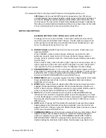
The elements of the Control Head (with reference to the identifiers above) are:
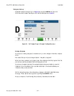
LCD Screen
. As long as the
SP38
system is powered on, the LCD screen
normally displays the compass heading, rudder angle, and mode of operation; it
can also be displaying desired heading, system status, other information, and
various menus. The overall set of items being displayed changes in response to
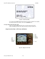
the various command buttons listed below (the screen shown above is the initial
screen, which appears for a few seconds after Power On).
BUTTON DESCRIPTIONS
ALL MODE BUTTONS: STBY, WORK, NAV, AUTO & P-STR
To change from one mode to another, a short press of almost one second is
required to prevent accidental mode changes. Double pressing a given mode
button accesses a shortcut menu pertinent to that mode, double press to exit
menu. Double press timing,
think; one, two.
1) ROTARY KNOB
- ALARM: Press Knob to silence an alarm. Knob press is an
operative ENTER.
When in MENUs, rotate to move between selections, press knob to gain
submenus, press to select an item for change. Rotate to change values or
choices, press to go back to item list, choice will be saved. Double press button
to exit menus.
When in AUTO mode, each click, left or right=1 degree of course change, left or
right. A quick spin of the knob, left or right=10 degrees of course change left or
right respectively. Pins are additive.3 spins =30 degrees of course change.
2)
STANDBY/ON/OFF
button. To Turn On, Press until the screen lights up. Short
Press STBY to enter Standby from a steering mode.
S
appears on screen. Press
and hold for OFF, screen will prompt with count-down to OFF. Double press for
shortcut to USER CONFIGURATION in main SETUP menu.
3)
BRIGHTNESS
button. Long press toggles from Day to Night palette. Short press
brings up brightness level scale on screen. Repeated short presses adjust
brightness level in a loop.
4)
WORK
button. Special mode to adapt rudder offset angle and movement when
engaged in slow speed work situations. Work is accessed when the pilot is in
AUTO or NAV only, See WORK mode section for more details. Double press to
access or cancel shortcut to WORK menu in main SETUP menu.
5)
NAV
button. Turns the Autopilot over to properly configured NMEA steering
instructions from the ship’s navigation system to an active waypoint, go to mark
or route.
N
will appear on screen. When in NAV, press again to toggle between 2
NAV screens. Double press to access or cancel shortcut to NAV menu in main
SETUP menu.
6)
AUTO
button. Pressing AUTO command the autopilot to assume the compass
heading being read at the moment as the commanded course to steer.
A
will
appear on screen. Change course with KNOB. Double press to access or cancel
AUTO menu from main SETUP menu.
7)
COMMAND (CMD)
button. Press to take command from any other station.
R
will
appear on the screen if another station is in command. Double press gains
access to complete menu trees for: SYSTEMMENU, NETWORK CONFIG.,
SETUP &FACTORY. SETUP is comprised of all shortcut menus gained by
double pressing the individual mode buttons. Double press to go back or exit.
Installation
Summary of Contents for SP38 Autopilot
Page 2: ......
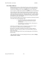
Page 14: ...Sitex SP38 Installation and Operation Document PN 29010101 V2r0 13 ...
Page 15: ...Sitex SP38 Installation and Operation Document PN 29010101 V2r0 14 Introduction ...
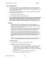
Page 16: ...Sitex SP38 Installation and Operation Document PN 29010101 V2r0 15 ...
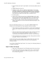
Page 26: ...Sitex SP38 Installation and Operation Document PN 29010101 V2r0 25 ...
Page 35: ...Sitex SP38 Installation and Operation Document PN 29010101 V2r0 34 Installation ...
Page 36: ...Sitex SP38 Installation and Operation Document PN 29010101 V2r0 35 ...
Page 74: ...Sitex SP38 Installation and Operation Document PN 29010101 V2r0 73 ...
Page 108: ...Sitex SP38 Installation and Operation Document PN 29010101 V2r0 107 ...
Page 109: ...Sitex SP38 Installation and Operation Document PN 29010101 V2r0 108 Advanced Operations ...
Page 110: ...Sitex SP38 Installation and Operation Document PN 29010101 V2r0 109 ...
Page 123: ...Sitex SP38 Installation and Operation Document PN 29010101 V2r0 122 Care and Maintenance ...
Page 124: ...Sitex SP38 Installation and Operation Document PN 29010101 V2r0 123 ...
Page 127: ...Sitex SP38 Installation and Operation Document PN 29010101 V2r0 126 Appendices ...
Page 128: ...Sitex SP38 Installation and Operation Document PN 29010101 V2r0 127 ...
Page 156: ...Sitex SP38 Installation and Operation Document PN 29010101 V2r0 155 Warranty ...
Page 157: ...Sitex SP38 Installation and Operation Document PN 29010101 V2r0 156 User Notes and Settings ...
Page 158: ...Sitex SP38 Installation and Operation Document PN 29010101 V2r0 157 ...

