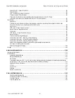
Speed Trip Pt – Speed Trip Point ...............................................................................................................94
Speed Source .............................................................................................................................................94
ALC - Automatic Leeway Correction ..........................................................................................................94
Thruster Assist / Thruster Gain ................................................................................................................. 94
These two functions are only available when the parameter is not set to “None.”
Complete instructions are included with the CT7 Thruster Interface. ....................................................... 94
NAV Mode .........................................................................................................................................................95
Nav Menu ...................................................................................................................................................96
The Nav menu contains a number of parameters used when operating the autopilot in NAV mode.
To access the Nav menu, double-press the NAV button. ......................................................................... 96
Nav Source ................................................................................................................................................96
XTE Limit - Cross-Track Error Limit ...........................................................................................................96
WayPt. Arrival - Waypoint Arrival ................................................................................................................96
Correction .................................................................................................................................................. 97
XTE Sense - Cross-Track Error Sense ...................................................................................................... 97
Max Correction .......................................................................................................................................... 98
Commanded Heading Displayed ............................................................................................................... 98
Correction set to CTS – Steering a Direct Bearing ................................................................................... 98
Correction set to XTE – Cross-Track Error Steering ................................................................................. 99
Correction set to Both – Steering To/Along a Track .................................................................................101
Refer to the Navigation System’s manual for signal quality measurements,
and ideas on making improvements.
Alternate Navigation Display .....................................................................................................................103
Dodge .............................................................................................................................................................103
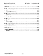
Advanced Operations ........................................................................................................108
Advanced Operations ......................................................................................................................................110
WORK Mode ................................................................................................................................................. 110
Automatic WORK Mode ...........................................................................................................................112
Manual WORK Mode ...............................................................................................................................112
Work Menu ..............................................................................................................................................113
The states shown are “Off”, “A_On” and “A_Rdy” (abbreviations for Automatic On and Automatic Ready,
respectively), or “M_On” and “M_Rdy” (Manual On and Manual Ready). ................................................113
Special Turns & Turn Menu .....................................................................................................................115
U-Turn .......................................................................................................................................................116
Circle Turn ............................................................................................................................................... 117
Fishzag ....................................................................................................................................................119
Station Lock/Unlock .................................................................................................................................121
Care and Maintenance .......................................................................................................1
22
Cleaning and Appearance .......................................................................................................................124
Protection of Wires and Cabling ..............................................................................................................124
Periodic Checks ....................................................................................................................................... 124
Fuse Replacement ....................................................................................................................................125
Sitex SP38 Installation and Operation
Table of Contents, List of Figures and Tables
Document PN
29010101
V2r0
-
8
-
Summary of Contents for SP38 Autopilot
Page 2: ......
Page 14: ...Sitex SP38 Installation and Operation Document PN 29010101 V2r0 13 ...
Page 15: ...Sitex SP38 Installation and Operation Document PN 29010101 V2r0 14 Introduction ...
Page 16: ...Sitex SP38 Installation and Operation Document PN 29010101 V2r0 15 ...
Page 26: ...Sitex SP38 Installation and Operation Document PN 29010101 V2r0 25 ...
Page 35: ...Sitex SP38 Installation and Operation Document PN 29010101 V2r0 34 Installation ...
Page 36: ...Sitex SP38 Installation and Operation Document PN 29010101 V2r0 35 ...
Page 74: ...Sitex SP38 Installation and Operation Document PN 29010101 V2r0 73 ...
Page 108: ...Sitex SP38 Installation and Operation Document PN 29010101 V2r0 107 ...
Page 109: ...Sitex SP38 Installation and Operation Document PN 29010101 V2r0 108 Advanced Operations ...
Page 110: ...Sitex SP38 Installation and Operation Document PN 29010101 V2r0 109 ...
Page 123: ...Sitex SP38 Installation and Operation Document PN 29010101 V2r0 122 Care and Maintenance ...
Page 124: ...Sitex SP38 Installation and Operation Document PN 29010101 V2r0 123 ...
Page 127: ...Sitex SP38 Installation and Operation Document PN 29010101 V2r0 126 Appendices ...
Page 128: ...Sitex SP38 Installation and Operation Document PN 29010101 V2r0 127 ...
Page 156: ...Sitex SP38 Installation and Operation Document PN 29010101 V2r0 155 Warranty ...
Page 157: ...Sitex SP38 Installation and Operation Document PN 29010101 V2r0 156 User Notes and Settings ...
Page 158: ...Sitex SP38 Installation and Operation Document PN 29010101 V2r0 157 ...


