75
1
ppr
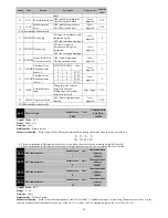
2200H
P2-01
The number of internal position
instruction 1 pulses low four
Initail value
Unit
Communication
Address
0
ppr
2201H
Control Mode
:
P
Range
:
P2-00
:
-30000
~
+30000
;
P2-01
:
-9999~+9999
Data size
:
16bit
Display mode
:
Decimal system
Parameter function
:
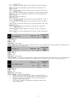
Set the target pulse number of first position moves.
The calculation formula is
:
Pr1 segment total pulse number
=
10000* P2-00 + P2-01
Please pay special attention to when computing, P2-00 and P2-01 are a symbol number.
For example
:
If the P2-00 input13, P2-01 input1050, set the target pulse number to 131050.
If the P2-00 input is 13, P2-01 input -1050, target pulse number is 128950.
If the P2-00 input -13, P2-01 input-1050, set the target pulse number 131050 reverse.
If the P2-00 input -13, P2-01 input 1050, set the target pulse number 128950 reverse.
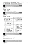
P2-02
The movement speed of internal position
command 1
Initail value
Unit
Communication
Address
100
rpm
2202H
Control Mode
:
P
Range
:
-9000
~
9000
Data size
:
16bit
Display mode
:
Decimal system
Parameter function
:
Set the speed of the first section of the position to run at a constant speed.
NOTE
:
1: set speed is positive, the motor in accordance with the number of pulses set forward, whereas
the motor according to the number of pulses set in reverse.
2: If the position pulse less, may not reach this speed when the motor running actually.
Therefore, please understand the meaning of the parameters
:
the upper limit of the operation
speed of the motor during the execution Pr1 segment position.
P2-03
After the completion of the Pr1 into the
Pr2 waiting time
Initail value
Unit
Communication
Address
1.0
S
2203H
Control Mode
:
P
Range
:
0.0
~
3000.0
Data size
:
16bit
Display mode
:
Decimal system
Parameter function
:
When P1-03=0 or 1
,
after the completion of the first stage position command, wait for this time then start the
implementation of the second stage position command. If P1-03 = 2, this parameter is invalid.
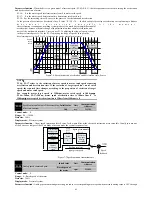
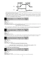
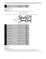
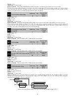
Figure 7-17 shows a schematic when run in command sequence. External terminal control mode switching schematic is similar but has the
difference. Please refer to P1-03 for explanation.
speed
/rpm
Pr1
...
P2-02
P2-03
Pr2
P2-06
Rated speed
Pr16
P2-63
P2-62
Position
10000*
P2_00
+
P2_01
Time
10000*
P2_04
+
P2_05
...
10000*
P2_60
+
P2_61
P2-07
P2-59
Figure7-17 Multi-position operation schematic
NOTE
:
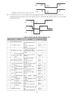
1: When using the internal multistage position, whether it is run by the command sequence or
external terminal switching mode, if you modify the current segment operating parameters,
the modified parameters will not be executed, will take effect when the next execution of the
segment.
2: When using an external terminal switching mode during the execution period of the position
command, the servo drive will not terminate execution of the current segment position
command due to DI sub-state changes.
3: When using the external terminal switching mode, after the current position instruction
execution is completed, the servo drive waits to receive the falling of CTRG, according to the
state of the terminal DI at that time, executes position instruction of the corresponding segment.


