97
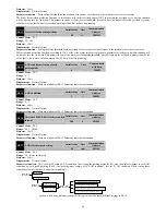
CRC parity
2
Slave responds
:
Slave address
1
Local address
command code
1
0x10
Read bytes
2
0x0000
-
0x0FFFF
Register data
2
0x0000
-
0x0008
CRC parity
2
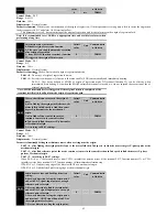
Command code 0x08: line diagnostics and settings
ADU Item
Byte No.
Range
Master requests:
Address of slave
1
0
-
0FEH
Command code
1
0x08
Sub function code
2
0x0000
-
0x0FFFF
data
2
CRC parity
2
Slave responds
:
Address of slave
1
Local address
Command code
1
0x08
Sub function code
2
0x0000
-
0x0FFFF
data
2
CRC parity
2
Note: the 0x08 command code is only used to check whether the line is connected.
8.5 Protocol Format Description
Address code
Servo drives slave address. The Setting range: 1-247.
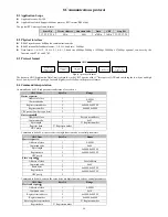
Function code
Function code
Function describe
03H
Read parameters and status byte of servo drive
06H
Write single function code or control parameter of servo drive
10H
Write several function codes or control parameters of servo drive
08H
Circuit diagnosis and setting
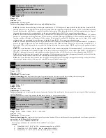
Allocation of Register Addresses
Name
Address Space
Description
Function
Code
0000H-0FxxH
High byte is function code group number, and high byte
address corresponding to P0-PF is 00H-0FH. And low byte is
group internal function code number.
For example: P3-00 corresponds to the address of 0300H.
2000H-2FxxH
If you want to save the modified parameters, which means to
modify the contents of the EEPROM, adding 2000H to
functional code address is OK.
For example: P3-00 corresponds to the address of 2300H
Remark
*: Some function parameters have two communication addresses, such as P1-00 have two communication addresses: 0100H and 2100H.
Beginning with address 0, it indicates that this parameter written to the RAM register of the drive, and can be executed immediately, but will not
be saved; Beginning with address 2, it indicates that this parameter written to the EEPROM of drive, can be executed immediately and saved;
*: If you require to frequently rewrite parameters frequently to EEPROM, due to the limit of writing cycles of EEPROM, EEPROM may be
damaged. Therefore, for parameters which need to be frequently rewritten via communication, please use RAM address, whose starting address
is 0. For example, in speed mode, when it need to transfer speed command in real time via the communication, the written address of speed
command must use 0300H, not 2300H.
*: For the parameters whose RAM register addresses are not listed, when using the address
starting with 0, the data will be received but will not be executed and saved. When these
parameters using EEPROM address, the data will be saved, but whether executed
immediately depend on parameter attributes.
CRC
Parity
Sending equipment calculates CRC parity value first, and then attaches it to the sending message. Upon receipt of the message, receiving
equipment will calculate CRC parity value again, and compare the operation result with received CRC parity value. If the two values are
different, it indicates that there is error during transmission.
Calculation process of CRC parity:
1)
Define a CRC parity register, and initialize it as FFFFH.
2)
Conduct XOR calculation between the 1st byte of sending message and the value of CRC parity register, and then upload the result to
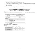
CRC parity register. Start from address code, the start bit and stop bit will not be calculated.

