79
1 P 5 08
2
1
/
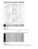
KVP
f
Hz
JL JM
JL
:
Load inertia
,
JM
:
Motor inertia
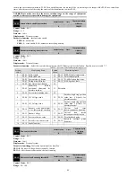
P5-05
Speed regulator integration time
constant
Initail value
Unit
Communication
Address
10.0
ms
2505H
Control Mode
:
P S
Range
:
0.1
~
3000.0
Data size
:
16bit
Display mode
:
Decimal system
Parameter function
:
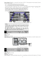
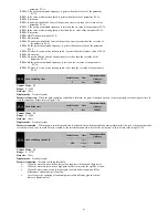
When the integral time of the speed regulator is increased, it can improve the speed response ability and decrease the
speed control deviation. However, it will produce vibration and noise when it is too large.
Speed loop integral can effectively eliminate the steady state error of the velocity, and the fast response is slight. The integral time constant
i
T
of
the speed loop is reduced under the condition that the mechanical system doesn‘t a produce vibration or noise, so as to increase the rigidity of
the system and reduce the error of the steady state. If the load inertia ratio is larger or mechanical system has resonance factor, it is necessary to
confirm that the integral time constant of the velocity loop is enough large, otherwise the mechanical system is easy to produce resonance. If the
load inertia ratio
G
is set correctly
/
L
M
G J
J
, the velocity integral time constant
i
T
is obtained by the following formula:
5000
(
)
2
(
)
v
Ti ms
f Hz
The greater the load inertia,the greater the time constant of the velocity integral under normal circumstances.
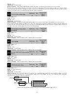
P5-06
Speed regulator proportional gain
fluctuation ratio
Initail value
Unit
Communication
Address
50
%
2506H
Control Mode
:
P S
Range
:
10
~
500
Data size
:
16bit
Display mode
:
Decimal system
Parameter function
:
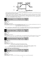
When the gain switching condition is satisfied, the rate of change for target speed regulator proportional gain
target speed regulator proportional gain
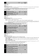
P5-07
Gain adjustment mode selection
Initail value
Unit
Communication
Address
0
-
2507H
Control Mode
:
P S
Range
:
0
~
2
Data size
:
16bit
Display mode
:
Decimal system
Parameter function
:
P5-07=0
:
Manual mode
The related parameters of position and speed regulator gain P5-00
、
P5-04
、
P5-05
and
load inertia ratio P5-08
all
set by the users
themselves.
The speed bandwidth is invalid under this mode.
When switching from automatic or semi-automatic mode to manual mode, these gain parameters (P5-00, P5-04, P5-05, P5-08)
will maintain the original value that semi-automatic mode automatically calculated.
P5-07=1
:
Semi-automatic mode (non-continuous adjustment)
Users only need to set speed bandwidth P5-11,
this system
can calculate the value of P5-00, P5-04, P5-05 based on it. At the
same time should be given appropriate P5-08Initail value, the actual value will automatically recognize and automatically
overwritten by the system at runtime.
After the system detects inertia becoming stable, stopping the identification of P5-08, and storing the results to P5-08.
P5-07=2
:
Automatic mode
(
continuous adjustment
)
Users only need to set speed bandwidth P5-11, this system can calculate the value of P5-00, P5-04, P5-05 based on it. The load
inertia ratio will automatically recognize by the system .
System estimate continuously the load inertia ratio, updated P5-08 in real time.
Use manual mode for the following
:
When using automatic and semi-automatic mode ineffective.
The mechanical parts do not connect firmly, for example, there is a reverse gap.
The mechanical rigidity is very low.
The load inertia ratio is too large (over 20 times), or too small (less than 3 times) .
The load inertia is large fluctuations.
There is a continuous low speed (less than 100RPM) operation.
The deceleration time is not more than 2000rpm/s.
The acceleration time of speed not less than 100RPM and not less than 2000rpm/s did not last for at least 50ms.
The acceleration and deceleration torque
is smaller than the friction torque.

