82
Not
satisfied
Switching
condition
Gain
combination
First gain
Delay time
Switching time
Second gain
Delay time Switching time
First gain
satisfied
Not
satisfied
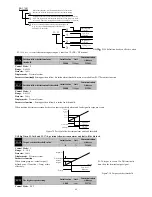
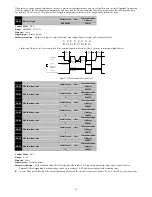
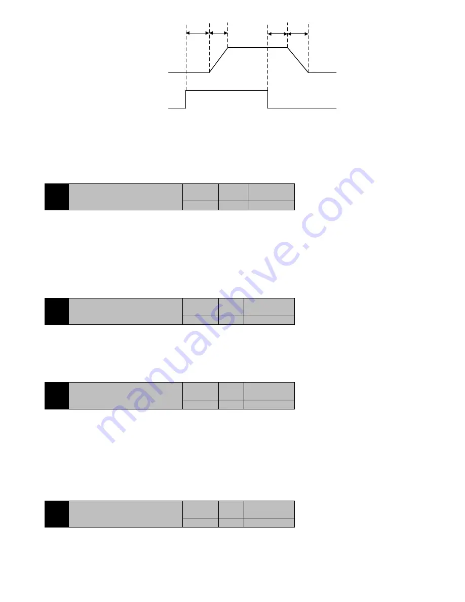
Figure7-20 Gain switching process
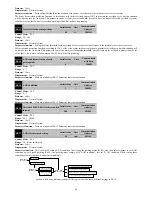
When the switching condition is satisfied, the gain is switched to second gain. If the switching condition is not satisfied during the second
gain operation, the gain is switched to a first gain.
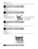
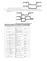
Switch condition change state must maintain the delay time setting by parameter P5-15 to be able to switch, so as not to switch by the
interference. When switching, the current gain combination is in accordance with the setting time of the parameter P5-14, the linear
smoothing gradient to the target gain combination, the various parameters of combination simultaneously changes, to avoid mechanical
shock caused by sudden changes of parameters. Once the switch is started, even if the change status of the switch is changing again, the
delay time can be recalculated after the switch is completed.
P5-17
Control loop coefficient
Initail value
Unit
Communicatio
n Address
4
-
2511H
Control Mode
:
P S
Range
:
1
~
32
Data size
:
16bit
Display mode
:
Decimal system
Parameter function
:
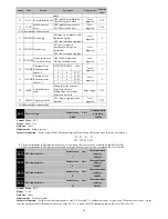
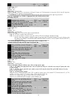
Only in P5-07=1, 2, that is, gain adjustment mode is semi-automatic and automatic mode, this parameter is effective. So
as to determine the relationship between speed bandwidth and position bandwidth .
Speed bandwidth= Position bandwidth*P5-17
There is no parameters about position bandwidth can be set. The parameters control based on the theory of automatic control that the speed
loop bandwidth should be at least 4 times than the position loop bandwidth. Generally do not adjust, especially not a small adjustment.
P5-19
Low frequency rigidity coefficient
Initail value
Unit
Communication
Address
1.0
-
2513H
Control Mode
:
P S
Range
:
0.5
~
4.0
Data size
:
16bit
Display mode
:
Decimal system
Parameter function
:
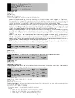
Only in P5-07=1, 2, gain adjustment mode is semi-automatic and automatic mode, this parameter is effective. It used to
set the rigidity of the speed loop at low frequency, that is the integral time constant of the speed regulator at low frequency. It‘s meaning is
:
P5-20
External disturbance resistance gain
Initail value
Unit
Communication
Address
0.0
%
2514H
Control Mode
:
P S
Range
:
-100.0
~
100.0
Data size
:
16bit
Display mode
:
Decimal system
Parameter function
:
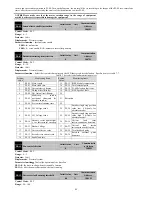
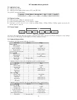
External disturbance compensation after disturbance observation
It used to reduce the speed change of load disturbance. Its meaning is:
Compensated torque =
Compensating torque
+
Observed disturbance quantity
*P5-20
After the disappearance of the observed disturbance, the torque will be cancelled immediately.
7.7 P6-xx Input and output(DI/DO)parameter
P6-00
DI Filter settings
Initail value
Unit
Communication
Address
2
ms
2600H
Control Mode
:
P S T
Range
:
0
~
20
Data size
:
16bit
Display mode
:
Decimal system
Parameter function
:
Set the filter time of the DI terminal, stop setting after motor stops, take effect immediately.


