


28
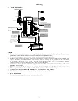
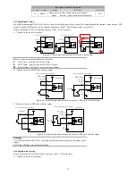
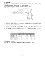
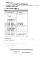
Pulse instruction
form
Logic state
Pulse waveform
P1-02=5
Negative logic
Forward
Reversal
PULSE
SIGN
T3
T1
T2
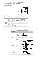
Table 4-6 Pulse input time parameter
Pulse mode
Maximum
input frequency
The minimum allowable width
Voltage
T1
T2
T3
T4
Differential
500Kpps
5V
Open collector
200Kpps
24V(MAX)
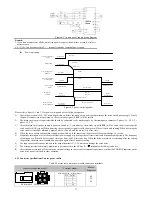
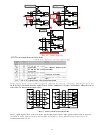
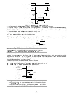
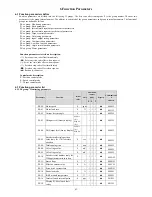
4.4.8.1 Position instruction pulse differential input mode
EA100
2KΩ
100Ω
100Ω
1
33
34
Upper computer
100Ω
100Ω
31
32
41
16
GND
PULSE
+
PULSE
-
SIGN
+
SIGN
-
The minimum
position instruction
pulse width is 1us
The maximum input
frequency is 500kpps
PE
GND
2KΩ
Figure 4-13 Position instruction pulse differential input mode wiring
Please ensure "2.8V
≤
(H level -L level)
≤
3.7V", otherwise the servo drive input pulse will be unstable. It will result in the following
situations:
Missing pulse when enter instruction pulse.
The instruction is opposite when enter instruction direction
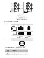
4.4.8.2 Position instruction pulse differential input mode Instruction direction
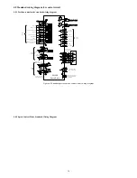
When using the servo internal 24V power supply
2KΩ
100Ω
100Ω
1
33
34
100Ω
100Ω
31
32
36
16
PULSE
-
SIGN
-
COM
+24V
+24V
PULHIP
PULHIS
+24V
power
supply
+24V
power
supply
2KΩ
100Ω
100Ω
1
33
34
100Ω
100Ω
31
32
36
16
PULSE
-
SIGN
-
COM
+24V
+24V
PULHIP
PULHIS
+24V
power
supply
+24V
power
supply
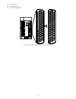
25
25
PULSE+
SIGN+
Servo drive
Servo drive
PULSE+
PE
PE
NPN
PNP
Open collector pulse position
instruction. The maximum input
frequency is 200kpps. The
minimum pulse width is 2.5us
25
25
2KΩ
2KΩ
Figure 4-14 open collector pulse input command wiring diagram (using the servo internal 24V)
When using the servo external 24V power supply


