


73
Filter type
Suitable
occasion
Advantages
disadvantages
is not suitable for frequent drift
occasions
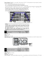
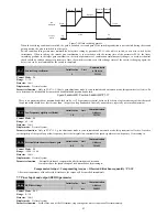
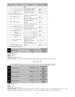
Notch
filter
gain
+
Notch depth
P1-50
resonance frequencyP1-49
=
Mechanical
response
gain
B.W
Resonance point was
suppressed
Mechanical
response
gain
B.W
Resonance
point
resonance frequencyP1-49
resonance frequencyP1-49
Constant
bandwidth
Figure7-14 The principle of vibration suppression using notch filter
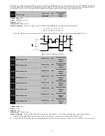
+
Mechanical
response
gain
B.W
Resonance point was
suppressed
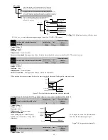
L
ow
pass
filter
gain
Frequency
-3db
0db
Cutoff
frequency and
P1-22
correlation
Mechanical
response
gain
B.W
Resonance
point
Resonance
frequency
=
Bandwidth reduction
Figure 7-15 The Principle of vibration suppression using low pass filter
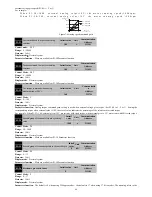
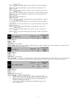
P1-53
Stop mode selection
Initail value
Unit
Communication
Address
0
-
2135H
Control Mode
:
P S T
Range
:
0
~
1
Data size
:
16bit
Display mode
:
Decimal system
Parameter function
:
set stop mode
P1-53=0
:
when servo OFF, free parking
P1-53=1
:
when servo OFF, slow down stop
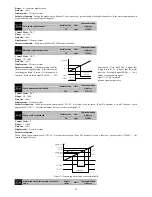
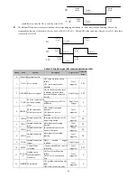
P1-54
Servo ON-
receive instruction delay time
Initail value
Unit
Communication
Address
200
ms
2136H
P1-55
Brake command - servo OFF delay time
Initail value
Unit
Communication
Address
200
ms
2137H
Control Mode
:
P S T
Range
:
0
~
500
Data size
:
16bit
Display mode
:
Decimal system
Parameter function
:
Please refer to section 3.7.2.
P1-56
Braking command action speed
Initail value
Unit
Communication
Address
50
rpm
2138H
Control Mode
:
P S T
Range
:
1
~
1000
Data size
:
16bit
Display mode
:
Decimal system
Parameter function
:
Please refer to section 3.7.2.
P1-57
Servo OFF- brake command waiting
time
Initail value
Unit
Communication
Address
500
ms
2138H


