Functions
2.5 Distance Protection
SIPROTEC, 7SD5, Manual
C53000-G1176-C169-5, Release date 02.2011
171
When using a personal computer and DIGSI to apply the settings, these can be optionally entered as primary
or secondary values.
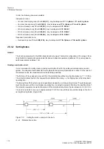
In the case of parameterization with secondary quantities, the values derived from the grading coordination
chart must be converted to the secondary side of the current and voltage transformers. In general:
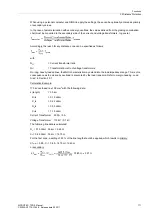
Accordingly, the reach for any distance zone can be specified as follows:
with
N
CT
= Current transformer ratio
N
VT
= Transformation ratio of voltage transformers
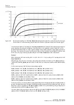
On long, heavily loaded lines, the MHO characteristic may extend into the load impedance range. This is of no
consequence as the pickup by overload is prevented by the load trapezoid. Refer to margin heading „Load
Area“ in Section 2.5.1.
Calculation Example:
110 kV overhead line 150 mm
2
with the following data:
s (length)
= 35 km
R
1
/s =
0.19
Ω
/km
X
1
/s =
0.42
Ω
/km
R
0
/s =
0.53
Ω
/km
X
0
/s =
1.19
Ω
/km
Current Transformer 600 A / 5 A
Voltage Transformer 110 kV / 0.1 kV
The following line data is calculated:
R
L
= 0.19
Ω
/km · 35 km = 6.65
Ω
X
L
= 0.42
Ω
/km · 35 km = 14.70
Ω
For the first zone, a setting of 85 % of the line length should be applied, which results in primary:
X1
prim
= 0.85 · X
L
= 0.85 · 14.70
Ω
= 12.49
Ω
or secondary:


