Functions
2.5 Distance Protection
SIPROTEC, 7SD5, Manual
C53000-G1176-C169-5, Release date 02.2011
158
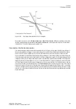
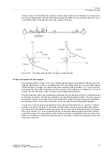
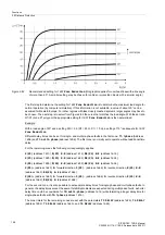
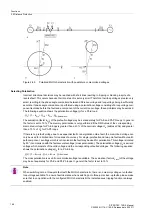
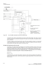
Figure 2-62
Recommended setting for
1607
Zone Reduction
(this graphic applies for overhead lines with a line angle
of more than 60°. A smaller setting may be chosen for cables or protected objects with a smaller angle)
The first step to determine the setting for
1607
Zone Reduction
is to determine the maximum load angle for
normal operation (by computer simulation). If this information is not available, a value of about 20° can be
assumed for Western Europe. For other regions with less closely meshed systems, larger angles may have to
be chosen. The next step is to select from Figure 2-62 the curve that matches the load angle. With the set ratio
R1/X1 (zone Z1 polygon) the appropriate setting for
1607
Zone Reduction
is then determined.
Example:
With a load angle of 20° and a setting R/X = 2.5 (R1 = 25
Ω
, X1 = 10
Ω
), a setting of 10° is adequate for
1607
Zone Reduction
.
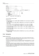
Different delay times can be set for single- and multiple-phase faults in the first zone:
T1-1phase
(Address
1605
) and
T1-multi-phase
(address
1606
). The first zone is normally set to operate without additional time
delay.
For the remaining zones the following correspondingly applies:
X(Z2)
(address
1613
),
R(Z2) Ø-Ø
(address
1612
),
RE(Z2) Ø-E
(address
1614
);
X(Z3)
(address
1623
),
R(Z3) Ø-Ø
(address
1622
),
RE(Z3) Ø-E
(address
1624
);
X(Z4)
(address
1633
),
R(Z4) Ø-Ø
(address
1632
),
RE(Z4) Ø-E
(address
1634
);
X(Z5)+
(address
1643
) for forward direction,
X(Z5)-
(address
1646
) for reverse direction,
R(Z5) Ø-Ø
(address
1642
),
RE(Z5) Ø-E
(address
1644
);
X(Z6)+
(address
1663
) for forward direction,
X(Z6)-
(address
1666
) for reverse direction,
R(Z6) Ø-Ø
(address
1662
),
RE(Z6) Ø-E
(address
1664
).
For the second zone, it is also possible to set separate delay times for single-phase and multi-phase faults. In
general, the delay times are set the same. If stability problems are expected during multi-phase faults, a shorter
delay time could be considered for
T2-multi-phase
(address
1616
) while tolerating a longer delay time for
single-phase faults with
T2-1phase
(address
1615
).
The zone timers for the remaining zones are set with the parameters
T3 DELAY
(address
1625
),
T4 DELAY
(address
1635
),
T5 DELAY
(address
1645
), and
T6 DELAY
(address
1665
).


