


Chapter
5
Operating Instructions
CLV 490 Bar Code Scanner
5-22
©
SICK AG · Division Auto Ident · Germany · All rights reserved
8 009 993/O824/20-12-2004
Electrical installation
For connecting the host interface via the CDB 420 or CDM 490 Connection Module, see
the Operating Instructions for the
"CDB 420 Connection Module"
(no. 8 010 001, German/
English) respectively the Operating Instructions for the
"CDM 490 Connection Module"
(no. 8 010 005, German/English).
Terminating the RS 422 interface:
The interface can be terminated in the Connection Module. See the Operating Instructions
for the
"CDB 420 or CDM 490 Connection Modules".
Activating the RS 232 interface:
The RS 232 interface can be activated with the "CLV-Setup" program:
1.
Choose the H
OST
I
NTERFACE
tab.
2.
Choose the RS 232 option from the H
ARDWARE
drop-down list under D
ATA
FORMAT
.
3.
Download the data to the CLV by clicking
in the toolbar.
The D
OWNLOAD
PARAMETERS
dialog box is displayed.
4.
Confirm the dialog box by choosing P
ERMANENT
.
The CLV uses the RS 232 version of the host interface.
Tip
The communication parameters can be changed, if necessary, on the H
OST
I
NTERFACE
tab.
To do so, change the values under D
ATA
F
ORMAT
and I
NTERFACE
P
ROTOCOL
.
5.5.5
Connecting the CAN interface
Connecting the CAN Interface 1 and configuring the CLV to use the device in the SICK-
specific CAN Scanner Network or in a CANopen network see the Operating Instructions
“Application of the CAN interface“
(no. 8 009 180, English edition).
5.5.6
Connecting the PC
The CLV is operated and configured with the PC-based "CLV-Setup" program. In order to do
so, you must connect the device to the PC via the terminal interface (auxiliary interface). Un-
like the host interface, the terminal interface has a permanent data format and a fixed data
transfer rate.
shows how the terminal interface is connected. The cable length
should not be more than 10 m (32.8 ft).
1.
Switch off the PC and power supply to the CDB 420 or CDM 490 Connection Module.
2.
Connect the PC to the internal, 9-pin "Aux" plug on the Connection Module.
To do so, use a 3-core RS 232 data cable (null modem cable), e. g. no. 2 014 054
(RxD and TxD crossed).
– or –
Without the SICK Connection Module:
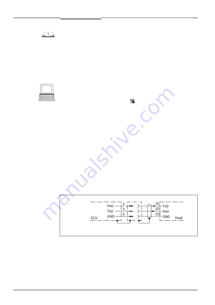
Connect the PC as shown in
Fig. 5-4:
Connecting the terminal interface
RS 232
( ) = 9-pin Sub D
plug on PC


