


128
Manual – IPOSplus®
12
P91x IPOSplus
®
parameters
P9xx IPOS Parameters
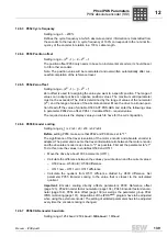
12.2.5 P916 Ramp type
This parameter specifies the type of the positioning ramp. This influences the speed or
acceleration characteristics during positioning.
INFORMATION
The following ramp types are not supported if P702 Motor category is set to "Linear":
• SPEED INTERPOLATION
• POSITION INTERPOLATION 12 BIT
• POSITION INTERPOLATION 16 BIT
Ramp type
Positioning characteristics
LINEAR
Time-optimal but block-shaped acceleration profile.
SQUARED
Softer acceleration and higher torque demand than LINEAR.
SINE
Very soft acceleration profile, required torque higher than with
SQUARED acceleration profile.
BUS RAMP
Setting for operation of drive inverter with master controller. This control-
ler generates a cyclical position setpoint that is written directly to the
position controller. The ramp generator is deactivated. The position
specifications sent cyclically by the external controller are interpolated
linearly. For configuration, one process output data word must be set to
"position HIGH" and another one to "position LOW".
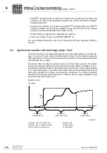
JERK LIMITED
Jerk limitation is based on the principle of the linear ramp. For jerk limita-
tion, the torque and, therefore, the acceleration is trapezoidal to limit the
jolting action. Over time, jerk limitation builds up the torque in linear form
during acceleration until the maximum value is reached. In the same
way, the torque is reduced again over time in linear form to zero. This
means that system vibrations can be virtually avoided. A setting range
can be selected from 0.005 ms to 2 ms (P933). The positioning time in
comparison to the linear ramp is extended by the set jerk time. The
acceleration and torque do not increase in comparison with the linear
ramp.
ELECTRONIC CAM
Activating the technology function "Electronic cam".
I SYNCHRONOUS OPERA-
TION
Activating the technology function "Electronic cam".
CROSS CUTTER
Activating the technology function "Cross cutter".
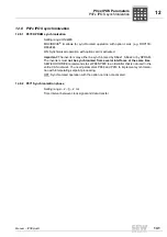
SPEED INTERPOLATION
The speed values sent cyclically by the external controller are interpo-
lated linearly.
•
Speed specification via process data:
–
Set P888
Synchronization time SBus
to 5 ms or 10 ms
–
Set the
P100 Setpoint source
to "SBus" or "Fieldbus"
–
You have to set a process output data word to "Speed".
•
Speed specification via SBus/SCOM object:
–
Set
P888 Synchronization time SBus
to 1 ... 10 ms.
–
Set the
P100 Setpoint source
to "BIPOL. FIXED SETPT".
–
You must not set a process output data word to "Speed".
–
Create a SCOM receive object (using the SCOM receive
command
→
IPOS
plus®
manual) with the target variable
SetpPosBus
(H499).
P
i
f
kVA
Hz
n


