


34
Manual – IPOSplus®
4
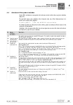
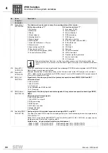
Overview of the system variables
IPOS Variables
490
WdogTimer /
WD.TIMER
Time for the user watchdog, READ and SET.
The watchdog timer counts down to 0. The WATCHDOG ON (WDON) command activates the timer and
determines the cycle time.
Value range: 0 ... 2
31
-1 ms.
491
SetpointPos /
SETP.POS.
Current setpoint position, READ.
IMPORTANT: System control variable Value must not be overwritten.
The setpoint position always has the following unit, regardless of the encoder pulse count per rev-
olution: 4096 Inc./motor revolution (encoder resolution
≥
512).
The current setpoint position represents the
absolute
position that is
currently
valid for position
control in the travel job in progress. The changes of the setpoint position result from the calcu-
lated travel profile taking into account the positioning ramp, the travel speed, the ramp type etc. Once the
requested travel has been completed and the drive is in standstill, H491 corresponds to H492.
Value range: -2
31
... 0 ... 2
31
-1 inc.
492
TargetPos /
TARGET POS
Current target position, READ and SET.
The target position always has the following unit, regardless of the encoder pulse count per revolution: 4096
Inc./motor revolution (encoder resolution
≥
512).
This variable represents the current target position of the travel job currently in progress. H492 displays the
position in its absolute form.
Example:
1. current drive position: 50000 Inc.
2. GOR NOWAIT #-8000 Inc.
3. current target position: 42000 Inc.
Value range: -2
31
... 0 ... 2
31
-1 inc.
If H492 is written directly (not using a GO command), H473, bit 19 "In position" remains set for up to 1 ms.
493
PosWindow /
POS.WINDOW
Positioning window, READ and SET.
H493 is identical to P922.
The positioning window defines a distance range around the target position (H492) of a travel or stop com-
mand (GOx or ASTOP TARGET POSITION). As soon as the drive has reached the positioning window, the
signal "IPOS IN POSITION" is generated. This message is available via a binary output that is to be parame-
terized to the "IPOS IN POSITION" function and in the system variable H473, bit 19. The "IPOS IN POSI-
TION" message is reset as soon as a GO command is placed.
The position window is always monitored provided an operating mode with IPOS is active (P700). The posi-
tioning accuracy is not affected by the value of the position window.
Setting range: 0 ...
50
... 2
15
- 1 increments
494
LagWindow /
LAG WINDOW
Lag error window, READ and SET.
H494 is identical to P923.
The lag error window defines the maximum permitted difference between the current setpoint position, which
the ramp generator specifies every 1 ms, and the actual position. If the specified value is exceeded, fault F42
(lag error) is triggered. The response to F42 must be set using parameter P834 "Response LAG ERROR".
Deactivation
: You can deactivate the lag error monitoring by setting the P923 Lag error window to 0.
Setting range: 0 ...
5000
... 2
31
- 1 increments
495
LagDistance /
LAG DISTAN
Lag distance, READ.
Value of the current lag distance in positioning (difference between setpoint and actual position).
Value range: 0 ... 2
31
- 1 increments
496
SLS_right /
SLS RIGHT
Software limit switch CW, READ and SET.
H496 is identical to P920.
Limits travel in a clockwise direction. The value is given in user travel units.
Setting range: - 2
31
...
0 user units
... 2
31
- 1 increments
497
SLS_left /
SLS LEFT
Software limit switch CCW, READ and SET.
H497 is identical to P921.
Limits travel in a counterclockwise direction. The value is given in user travel units.
Setting range: - 2
31
...
0 user units
... 2
31
- 1 increments
498
RefOffset /
REF.OFFSET
Reference offset, READ and SET.
H498 is identical to P900.
The reference object allows for a shift of the machine zero without physically shifting the reference mark. The
following applies:
Machine zero = reference po reference offset
The drive moves to the reference point during the reference travel and stops there. After the reference travel,
the machine zero is calculated with reference point and reference offset.
The reference offset is given in user travel units.
Setting range: - 2
31
...
0
... + 2
31
- 1
No.
Name
Compiler /
Assembler
Description
P
i
f
kVA
Hz
n
P
i
f
kVA
Hz
n


