


Manual – IPOSplus®
29
4
Overview of the system variables
IPOS Variables
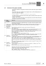
4.2
Overview of the system variables
Some IPOS variables are assigned set functions and are referred to as system variables
(page 25).
The symbolic names are available in the Compiler when one of the following lines is in-
serted at the start of the program:
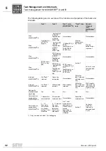
The following table describes the function of the system variables and their names in the
Compiler and Assembler.
Variables in the range specified that are not assigned are reserved for internal functions
and cannot be used for user variables.
#include <constb.h> //symb. name MOVIDRIVE B system variables
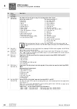
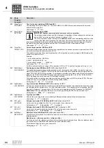
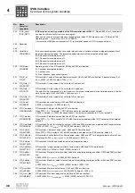
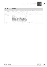
No.
Name
Compiler /
Assembler
Description
128
This variable can be used in a user-specific IPOS program. The variable is used by the application modules to
store the program identification.
360
...
452
Variable range for
internal synchro-
nous operation or
electronic cam
This variable range is assigned additional system variables if the technology options internal synchronous
operation or electronic cam are used. In all other cases, these can be used by the user as required.
453
ModuloCtrl /
MODULOCTRL
Control word for the modulo function (see also modulo function and IPOS parameter).
Bit 0 TargetReset_Off
Bit 0 = 0: The current positioning task is deleted (ModTagPos is set to ModActPos) if the positioning operation
is interrupted (for example, if the enable is revoked or if the controller inhibit or stop bit is set).
Bit 0 = 1: The target position is held even if the enable has been revoked or if the controller inhibit or the stop
bit has been set. If the drive is enabled again, it continues with the positioning process.
Bit 1 TargetGAZ_Select
Bit 1 = 0: Standard setting, 360° output corresponds to 2
16
incr.
Bit 1 = 1: Setting for increasing the resolution: 360° corresponds to the product from modulo numerator P961
x modulo encoder resolution P963. Positioning cannot be performed over several revolutions.
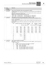
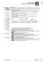
454
ModTagPos /
MOD.TAGPOS
Modulo target position
If a changed value is written to the modulo target position for an enabled inverter, positioning begins in output
units. The position setpoint (for H453.1 = 0) is set in 16 bit resolution in the unit H454 MODTAGPOS = k x
360° + 0 ... 360°= k x 2
16
+ 0 ... (2
16
-1) (k = number of complete revolutions).
Once a new value has been written to the variable, only the target position within a revolution is visible in vari-
able H454. We recommend that you also write the new value to a temporary variable for improved diagnos-
tics.
Once position 454 has been written, the firmware calculates an incremental target H492. This causes H473 bit
19 "In position" to remain set for up to 1 ms.
455
ModActPos /
MOD.ACTPOS
Modulo actual position
The current modulo actual position moves (in 16 bit resolution when H453.1 = 0) between 0 and 2
16
incre-
ments (0° and 360°).
456
ModCount /
MOD COUNT
Increments within a modulo revolution before scaling to the output.
Display value of the internal temporary result when the incremental encoder value H509/H510/H511 (IPOS
encoder value) is converted to the modulo actual position H455.
For H456 = (IPOS encoder value) MOD (P961 x P963)
H455 = H456/(P961 x P963) x 2
16
(prerequisite: H453, bit 1 = 0)
See section "Modulo positioning". If 0 is written to H456, H455 is set automatically to 0.
P
i
f
kVA
Hz
n
P
i
f
kVA
Hz
n


