Schleuniger CoaxCenter 6000 Reference Manual Download Page 37

5. Product description

Reference Manual |Edition 5.0 (09-2016) |

CoaxCenter 6000

37 | 194

CAUTION

Personal and property damage when product is operated by

untrained or not properly trained personnel.

Employment of insufficiently qualified personnel by ignorance in handling the

product and their potential hazard may lead to personnel injury and property

damage.

Operate the product only by trained personnel

Carry out regular staff training

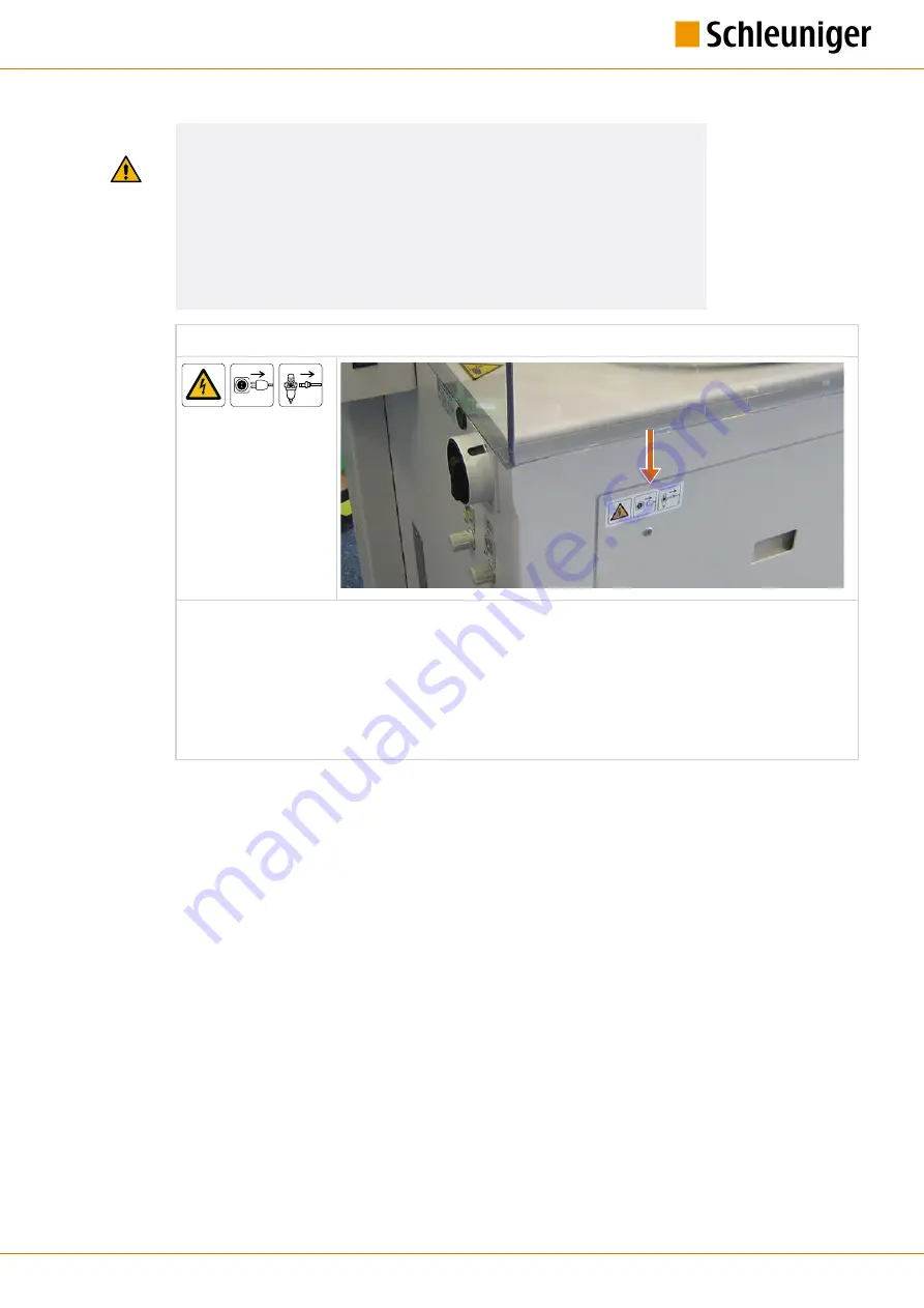
Unplug machine from the mains- and compressed air supply

There is a danger of electric shock by contact with parts inside the machine and on the mains con-

nection. Touching electric components can cause injury to the operator personnel. Unintentional

operation of pressurized components, or unintentionally escaping compressed air can cause injury.
Therefore always before opening the machine:

Turn off the main switch, block against switching on again and disconnect the machine from the

mains (for hard wired machines, the main switch serves as a mains disconnecter).

Unplug the machine from the compressed air supply.

Summary of Contents for CoaxCenter 6000

Page 1: ...Reference Manual Edition 5 0 09 2016 CoaxCenter 6000 1 194 CoaxCenter 6000 Automatic Coaxial Cable Cut Strip Machine Reference Manual Software Version 2 2x Edition 5 0 09 2016...

Page 2: ...c 87 Colin Drive Manchester NH 03103 USA P 1 603 668 81 17 F 1 603 668 81 19 sales schleuniger com www schleuniger na com Schleuniger Japan Co Ltd 1726 15 Higashi Naganuma Inagi city Tokyo Japan P 81...

Page 3: ...e models and options Machine overview and description on the processing and function modules Page 23 Page 29 INSTALLATION FIRST COMMISSIONING Step by step instruction for the installation and commissi...

Page 4: ...Topic list 4 194 Reference Manual Edition 5 0 09 2016 CoaxCenter 6000...

Page 5: ...0 SPARE PARTS 14 2 SAFETY 15 2 1 TARGET AUDIENCES 15 2 2 WARNING NOTICES 16 2 3 CAUTION PROPERTY DAMAGE 16 2 4 GENERAL SAFETY NOTES 17 2 5 RESIDUAL RISKS 17 2 6 SAFETY SYMBOLS IN MANUAL 18 2 7 SAFETY...

Page 6: ...43 5 3 3 General units 43 5 3 4 Optional stations 44 5 3 5 Connections interfaces 46 5 4 DELIVERY ACCESSORIES 47 5 4 1 Accessories 47 5 4 2 Options 47 6 INSTALLATION FIRST COMMISSIONING 49 6 1 SAFETY...

Page 7: ...indow 80 8 2 7 Quantity of articles 80 8 2 8 Produced articles 80 8 2 9 Remaining articles 80 8 2 10 Reset production counter 80 8 2 11 Batch on off 81 8 2 12 Total batch 81 8 2 13 Remaining batches 8...

Page 8: ...4 11 6 DIAGNOSTIC FUNCTIONS IN THE CONTROL SOFTWARE 115 11 6 1 Overview 115 12 DATA MANAGEMENT UPGRADES SERVICES 123 12 1 OVERVIEW 123 12 2 DATA BACKUP 124 12 3 DATA RESTORE 124 12 4 UPGRADE OF THE CO...

Page 9: ...ference Manual Edition 5 0 09 2016 CoaxCenter 6000 9 194 16 3 LUBRICATING GREASE SDS MICROLUBE GBU Y 131 164 16 4 LUBRICATING SPRAY TREND ULTRA PLUS EXTRA 175 16 5 TABLE OF GRAPHICS 185 16 6 TABLE OF...

Page 10: ...Table of contents 10 194 Reference Manual Edition 5 0 09 2016 CoaxCenter 6000...

Page 11: ...TRUCTIONS We have taken every possible measures to ensure the accuracy and completeness of this documenta tion Since errors can be avoided despite the diligence never fully we are always grateful for...

Page 12: ...neral ref erence work for the personnel Contents Safety Description of the product Shipping Commissioning Operation Troubleshooting Maintenance Disposal Target audiences Operator Qualified personnel T...

Page 13: ...on Screen title menu Screen titles and menus are represented in the text in quotation marks Schleuniger Product names and company Product and company names are represented italic 1 5 Legend Page 13 Cr...

Page 14: ...ight law of the manufacturer 1 9 1 Trademarks CAYMAN the CAYMAN logo IGUANA and the IGUANA logo are trademarks of Schleuniger The control software S QAR is a trade mark of Schleuniger Windows is a reg...

Page 15: ...target audiences must have the following skill Thus have the competence to carry out certain activities Operating company Qualification Higher level juristic person Authority to give directives Define...

Page 16: ...ked with the warning banner and the appropriate danger symbol The following three endangering levels are primarily distinct by the sig nal word Compulsory comply the warning notices to avoid accidents...

Page 17: ...e instructions given in this manual Maintenance and modification work must be carried out by appropriate qualified personnel 2 5 RESIDUAL RISKS With the use of technical products are dangers associate...

Page 18: ...parts inside the machine and on the mains socket Therefore before opening the machine always switch off the main switch and unplug it from the mains Touching electric com ponents can cause injury to...

Page 19: ...safety barriers Do not break in the emergency stop link between the processing machine and the peripheral devices in a production line 2 9 RETROFITTING Without written permission of Schleuniger do no...

Page 20: ...nsportation of the product can lead to property damage Handle the packaging with care Observe the packaging signs Wherever applicable remove the packaging not before placing on site of operation Move...

Page 21: ...N Check the goods immediately after receiving for completeness and loss during shipment On recognizable loss during shipment proceed as follows Do not accept the delivery or only with retentions Decla...

Page 22: ...3 Transportation 22 194 Reference Manual Edition 5 0 09 2016 CoaxCenter 6000...

Page 23: ...t be treated in the following way Cut through Incision Stripping Crimping Quality control Tinning See also chapter 5 Product description Page 29 As limits the areas in the technical data apply Any oth...

Page 24: ...09 2016 CoaxCenter 6000 4 2 DIMENSIONS AND WEIGHT Fig 1 Measures base layout Description Value Unit Weight Net base machine 410 kg Measures Length 1300 mm Length including wire straightener and stacke...

Page 25: ...FOR THE COAXCENTER 6000 Position of center of gravity Fig 2 Position of center of gravity During transportation observe the position of center of gravity Packaged observe the markings on the packaging...

Page 26: ...uter diameter 5 5 mm Min cross section 40 0 005 AWG mm2 Max cable length with active stacker also greater length available 1000 mm Min cable length stripping length 15 mm Max stripping length with spe...

Page 27: ...t Fig 4 Elevation 4 6 RATING PLATE In order to ensure efficient support for our part we ask the customer on any requests to always com municate the exact content on the rating plate The rating plate w...

Page 28: ...enter 6000 Made in Switzerland Serial No Bierigutstrasse 9 CH 3608 Thun Switzerland 50 60 Hz 1 3 4 7 410 kg 5 1 Year 2016 Power rating 100 120 VAC Weight Fuses 2 x T10 AH 800 VA 2 6 200 240 VAC 2 x T1...

Page 29: ...via the control software S QAR on a menu guided touch screen All production data inclusive 3D images of the quality control can be saved and recalled at all times Sample set up Crimping Machine Q Cam...

Page 30: ...unit with grippers Feeding of raw material to the individual stations Cutting unit with V blades and air jet unit Cutting through the raw material and blow off of waste piece Stacker Depositing of pro...

Page 31: ...ting unit control software 2 USB connector 3 Safety cover 4 Processing stations 5 Pressure control collector 6 Stacker 7 Control compartment electronics 8 Maintenance unit compressed air 9 Compressed...

Page 32: ...4 Reference Manual Edition 5 0 09 2016 CoaxCenter 6000 5 2 2 Further elements 1 2 3 4 Fig 6 Elements on left machine cover 1 Mains fuses 2 Line disconnecter 3 Compressed air control feeding unit 4 Com...

Page 33: ...uct description Reference Manual Edition 5 0 09 2016 CoaxCenter 6000 33 194 5 2 3 Power and compressed air connector 2 1 3 Fig 7 Power compressed air 1 Compressed air input 2 Maintenance unit 3 Power...

Page 34: ...Fig 8 Main view stations viewed from top 1 Wire straightener 2 Feeding unit 3 Swivel arm unit gripper side 1 4 Cutting unit 5 Q Cam 360 side 1 6 Rotary incising unit side 1 7 Swivel arm gripper side...

Page 35: ...ion 5 0 09 2016 CoaxCenter 6000 35 194 Interfaces control box rear 4 5 6 7 1 USB connector 2 SC memory card slot 3 Swiveling mechanism operating unit 4 Connector operating unit 5 ETHERNET interface 6...

Page 36: ...y appliances shown in the next figure 1 3 2 4 Fig 9 Safety appliances 1 Safety cover 2 Mains disconnecter 3 Emergency stop button 4 Safety cover switch 5 2 7 Danger zones The dangerous zones on the Co...

Page 37: ...ff training Unplug machine from the mains and compressed air supply There is a danger of electric shock by contact with parts inside the machine and on the mains con nection Touching electric componen...

Page 38: ...r of injure hands Danger of injury when grasping into during closing the hood or during the production Escaping processed articles On the outlet the produced articles are fed at high speed out of the...

Page 39: ...work the mains disconnecter must be turned off and locked against switching on again with a locker To switch on the machine turn the mains discon necter CW WARNING Electric shock There is a risk of an...

Page 40: ...e emergency stop button for normal system stop Disregarding may lead to property damage on the product Use the emergency stop button only in an emergency cases Safety cover open close Through the two...

Page 41: ...ol can be locked against inad vertent manipulation by the key switch con tained in the accessories Cover safety switch The safety switch is coupled with the safety cov er The production cannot be star...

Page 42: ...t Stacker Extending the tray for removing the batches Collector station Contact pressure of picker The maximal operating pressure should be adjusted on the pressure valve 1 to not higher than 7 bar 0...

Page 43: ...ipper side with the lever 4 The standard guides are contained in the acces sory kit 5 3 3 General units Swivel arm unit gripper The raw material is fed forwards through the guide 1 and next to the gri...

Page 44: ...according to the setting in the control software Via the key on the stacker unit the tray can be for taking away the article batch be extended to the right out of the machine This is a pneumatic acti...

Page 45: ...must be emptied regularly see chapter 13 3 Empty waste container rotary incising unit Page 129 Outworn blades of the rotary incising unit can be replaced see chapter 13 3 Blade change rotary incising...

Page 46: ...lever 3 down by hand On the side there is as mentioned in the over view an additional compressed air valve 4 where the contact pressure of the picker is adjusted 5 3 5 Connections interfaces Power co...

Page 47: ...others can permanently be saved 5 4 DELIVERY ACCESSORIES Exclusively use original spare parts of the manufacturer See Packing list Register 1 and document Parts Catalog 5 4 1 Accessories The CoaxCente...

Page 48: ...5 Product description 48 194 Reference Manual Edition 5 0 09 2016 CoaxCenter 6000...

Page 49: ...amage The following instructions must be carried out in the listed sequence and warning signs must be observed Safety relevant points The following security relevant points have to be mentioned specia...

Page 50: ...t truck 6 2 2 Power connection If the machine is not already equipped with the country specific mains connector it must be replaced according to the safety regulations by a technical specialist Observ...

Page 51: ...exactly aligned 4 Connect the power cord 5 to the mains 5 Switch on the power disconnecter 3 6 Connect the machine to the compressed air supply 4 Adjust the compressed air valve on the maintenance uni...

Page 52: ...he deflector sheet 14 Fixate the deflector sheet with the second locking lever 15 Put the stacker channel onto the stacker unit and hook in 16 Plug in the stacker unit to the appropriate connector of...

Page 53: ...connector cable of the operating unit through the opening 20 Hang up the cable bellow the arm and feed down to the control box 21 Plug in the cable of the operating unit on the rear of the control bo...

Page 54: ...ce Manual Edition 5 0 09 2016 CoaxCenter 6000 6 2 4 Mounting options Wire straightener 1 Disassemble the entry guide 2 Screw on the wire straightener to the con trol box with the four hex screws Tower...

Page 55: ...h the rotary incising unit on both sides For our sample the CoaxCenter 6000 is equipped with the following components Rotary incising unit Q Cam 360 Wire straightener unit Stacker unit The article sha...

Page 56: ...ol software has been initialized The start screen is displayed quickly then the log on screen appears 3 Touch the password field The alphanumeric touch keyboard pops up 4 On the touch keyboard enter 1...

Page 57: ...Adjust the compressed air valve as follows Adjust the pressure of the gripper to 1 5 bar 0 15 MPa 1 Adjust the pressure of the feeding belts to 1 bar 0 1 MPa 2 The compressed air pressure of the gripp...

Page 58: ...rst commissioning 58 194 Reference Manual Edition 5 0 09 2016 CoaxCenter 6000 6 3 2 Article programming 1 LEAVE SCREEN 2 Touch new article 3 On the touch keyboard enter the name of the article Cable A...

Page 59: ...anual Edition 5 0 09 2016 CoaxCenter 6000 59 194 5 Touch the list line of the just created arti cle Back to the article editor 6 RAW MATERIAL EDITOR The Raw Material editor is shown 7 Enter the values...

Page 60: ...type is shown 10 Select application type1 3 layers full strip Back to the article editor 11 Touch EDITOR APPLICATION RIGHT 12 Enter the stripping length according to the screen Bellow the article the...

Page 61: ...sing values for the jack et 15 LEAVE SCREEN 16 Change the Processing values for the shield 17 LEAVE SCREEN 18 Change the Processing values for the die lectric 19 LEAVE SCREEN 20 Change the global valu...

Page 62: ...e article editor 26 Touch EDITOR APPLICATION LEFT Enter the same values from procedure step 12 for the left end length Processing tolerance 27 LEAVE SCREEN 28 Touch PROCESSING EDITOR The Processing sc...

Page 63: ...2 35 Enter the values for the swivel arm 2 as for swivel arm 1 36 Change to the tab Options 37 Enter the values for the options according to the screen 38 LEAVE SCREEN Back to the article editor 39 I...

Page 64: ...guides loading raw material 1 Move the safety cover of the machine up 2 Mount the inlet guide 2 5 and fixate with the knurled screw 3 Mount the main guide 2 5 between feeding belt and gripper and fixa...

Page 65: ...hand through the entry guide up to one third of the feeding belts Notice The feeding belts can only be closed via the control software 7 Touch LOAD on the screen The feeding belts are closing The raw...

Page 66: ...ter 7 5 8 1 5 Mode Page 75 4 Start the total production with START The first 10 articles are produced 1 batch Then the production is stopped The next batch must be confirmed with OK 5 Change to the ta...

Page 67: ...o chapter 5 2 7 Danger zones Page 36 7 2 SWITCHING ON THE MACHINE 1 Turn the power disconnecter on the left of the machine CW 2 Open the main compressed air valve 3 Wait until the control software S Q...

Page 68: ...on the function mode Keys and its state and other elements can be distinguished by means of a color scheme NOTICE Property damage touch screen Operating the touch screen with sharp objects may damage...

Page 69: ...s and for logging on to a different user level 7 5 4 Navigation area In the upper part within the navigation area the selection keys for the main screens are located As there is often not enough space...

Page 70: ...een e g Raw Material or Processing editor By touching a certain key a drop down list pops up where the programmer can select preset values 7 5 6 Footer area In the footer area there are keys for the c...

Page 71: ...entry field 3 is touched directly a keyboard pops up in which the numeric value can be entered via the numer ic keys The entry is confirmed with RETURN 1 or however dis carded with CANCEL 2 If the va...

Page 72: ...ing mode In this case normally the field disappears completely Inch mm All values in fields containing length units are in Inch or Millimeter The length unit to be used has to be set in the Configurat...

Page 73: ...omponents are to be calibra ted Article management Here data in tabular form are shown e g the programmed saved articles from the article library In the next figure an example of a library is displaye...

Page 74: ...the header area of the touch screen the keys for the production control of the CoaxCenter 6000 are located Production keys Load unload A raw material is loaded automatically on the machine Therewith...

Page 75: ...the production continues automatically but much slower than in normal operation Each step is initiated with a single touch of STEP BY STEP Test mode We produce normally but without tolerance check Ste...

Page 76: ...hen access all commands and parameter settings enabled for this level User level programmer The user is logging in to the user level Programmer with a password and can then access all commands and par...

Page 77: ...09 2016 CoaxCenter 6000 77 194 Keys in the info area In the header line of the touch screen we find additional data 1 Version of the control software 2 Actual system date time 3 Global production spee...

Page 78: ...7 General handling operation 78 194 Reference Manual Edition 5 0 09 2016 CoaxCenter 6000...

Page 79: ...and batches are shown here 8 1 OVERVIEW ARTICLE EDITOR 1 2 3 5 9 7 6 8 10 15 13 11 16 12 13 17 4 18 19 1 Raw Material editor 2 Processing editor 3 Wire length 4 Correction value 5 Application type le...

Page 80: ...Defines how the left and right end shall be processed Touching the key opens the application editor For more information see chapter 8 5 Applications Page 86 8 2 6 Application editor window Removes t...

Page 81: ...aining batches Shows the amount of batches still to be produced since the last production start The value can be set back to Total batch with the command RESET PRODUCTION COUNTER 8 3 RAW MATERIAL EDIT...

Page 82: ...on the feeding belts speed acceleration deceleration Swivel unit Swivel unit axis Settings which concern the swivel arm movement and positioning on the stations speed acceleration deceleration cable o...

Page 83: ...value Deceleration This setting changes the deceleration of drives while feeding forth and back the raw material whereas 0 is the smallest and 100 the largest selectable value 8 4 3 Swivel unit side 1...

Page 84: ...not be selected to height to prevent the material of sag It should be always larger then the total stripping length spare e g rotary incising unit distance between gripper and blades Gripper Guide pos...

Page 85: ...ering Pre centering the blades while feeding Is a centering aid and the processing time is shortened default setting Centering off The blades open fully the pre centering may scratch the raw material...

Page 86: ...al strip jacket full strip shield partial strip dielectric 5 3 layers partial strip jacket full strip shield dielectric 6 3 layers full strip jacket shield partial strip dielectric 7 3 layers camera c...

Page 87: ...rocessing shield 8 Processing dielectric Settings Tolerance limits on off Here we define if the tolerance values entered in the tolerance editor shall be monitored and evalu ated by the Q Cam 360 Stri...

Page 88: ...alues Defines the upper and lower length tolerance limits on the individual layers relevant for the inspection with the Q Cam 360 Length limit values Defines the upper and lower diameter tolerance lim...

Page 89: ...can be unhindered be moved forth and back Contact opening Opening at the time the raw material is clamped by the centering unit during incising Select this value in a way that the material is clamped...

Page 90: ...diameter Determines the incision depth of the blade into the appropriate layer Incise speed Determines the incising speed of the blades whereas 0 is the smallest and 100 the largest selectable value...

Page 91: ...is helpful to wait a specified time after the incision Thus the insulation is cut properly With extremely flexible materials a longer pause results in proper cuts The value is set in milliseconds ms...

Page 92: ...the incision Thus the insulation is cut properly With extremely flexible materials a longer pause results in proper cuts The value is set in milliseconds ms Way back After incising the blades travel...

Page 93: ...t or right on the article The second key activates the second window on the selected side The second window can only be activated if the first window is active Position On which position from left or...

Page 94: ...1 2 3 5 6 1 Status 2 Mode 3 Statistics 4 Process 5 Production stop 6 Q Cam 360 Analysis 8 6 1 Status Processing type and file name of the article 8 6 2 Mode Step by step After each touch of this key...

Page 95: ...or more layers of an article are out of tolerance the value of the corresponding layer is displayed in red color If successively three articles are out of tolerance the machine stops the production j...

Page 96: ...tion can be selected 1 Then it is displayed bellow the article view 2 The crimp applications can be for using at a later time be saved By touching the key 1 the selection window for the crimp applicat...

Page 97: ...s production Reference Manual Edition 5 0 09 2016 CoaxCenter 6000 97 194 Detailed description for setting up the crimp application depends on the used crimping machine and can be found in the Referenc...

Page 98: ...8 Programming of articles production 98 194 Reference Manual Edition 5 0 09 2016 CoaxCenter 6000...

Page 99: ...2 3 4 5 6 7 8 1 1 Wire end monitoring 2 Pre processing device 3 Guide 4 Wire processing modules 5 Stacker 6 Network 7 System time date 8 Operating units 9 1 2 Description The keys above and bellow the...

Page 100: ...ivel arm unit side 1 5 Cutting unit 6 Swivel arm unit side 2 7 Rotary incising unit side 2 8 Q Cam 360 side 2 9 Crimping unit side 1 10 Wire bundler Q Cam 360 Swivel arm handing over Calibration The c...

Page 101: ...9 Configuration settings Reference Manual Edition 5 0 09 2016 CoaxCenter 6000 101 194 Backlight AOI collecting area...

Page 102: ...ed Rotary incising unit Centering axis Calibrate The calibration of the centering on the rotary incising unit is carried out via a wizard see chapter 13 4 2 Calibration rotary incising unit Page 138 R...

Page 103: ...on the cable type be calibrated For this a special calibration wire AWG 36 is loaded This wire is produced and analyzed in the Q cam The measured length of the stripped inner conductor then is compar...

Page 104: ...Cali bration cutting unit Page 145 Reference position Display of the calibrated value Intersect Value to intersect the raw material Crimping unit This defines all settings according to the crimping un...

Page 105: ...Pushing Position of the bundler Wire bundler unit Calibrate The calibration of the swivel arm position to the bundler is carried out via a wizard see chapter 13 4 2 Calibration rotary incising unit Pa...

Page 106: ...The data collected by the Q Cam 360 can be sent to a PC for analyzing This is done via the ETHERNET network All settings for the transmition to the PC IP address subnet mask are defined here System ti...

Page 107: ...to be altered first before using it See chapter 6 Installation first commissioning Page 49 To prevent the handling by unauthorized personnel hence the access on certain user levels can be restricted...

Page 108: ...rmat 4 Date format 10 2 1 User interface Here the language of the user interface can be determined 10 2 2 Units Length units Setting of the length unit used during article programming wire length pull...

Page 109: ...e changed individually on each user level Initial factory default passwords are programmed Touch Change password The password can be changed individually for each user level The new password can be en...

Page 110: ...10 User interface user levels 110 194 Reference Manual Edition 5 0 09 2016 CoaxCenter 6000...

Page 111: ...In case of an unrecoverable fault contact your local Schleuniger distributor see Page 2 Thereby always report the software version number Additionally inform about the selected raw material type stri...

Page 112: ...tact pressure Replace feeding belts Reduce tension force to the wire straightener Bad incising quality Outworn blades Elastically insulation Wrong blade type Replacing blades Increase the pause in the...

Page 113: ...firmed messages These are errors warnings and information which occurred during the last production run see also chapter 7 5 7 6 Dialog window Page 72 A total of 100 messages can be displayed Current...

Page 114: ...mory Error Here the articles together with a time stamp are entered which are declared as faulty dur ing production A total of 500 errors can be displayed In the text right the time of the event is di...

Page 115: ...condition Personnel qualification The instructions in this chapter must be carried out by qualified personnel CAUTION Risk of injury by improper manipulation When manipulating in the diagnostics scree...

Page 116: ...tary incising unit side 2 9 Q Cam 360 side 2 10 Collector Crimping unit Display of information and direct manipulation of the crimping unit Press Reference position Perform an initialization homing on...

Page 117: ...n Moves the centering mechanism up or down Sensor upper Display when the centering is up Sensor lower Display when the centering is down Q Cam 360 Display of information and direct manipulation on the...

Page 118: ...11 Diagnostics troubleshooting 118 194 Reference Manual Edition 5 0 09 2016 CoaxCenter 6000 Schnapshot Manual production of an image Focus Measuring the focus on the Q Cam...

Page 119: ...eference position Reference position Perform an initialization homing on the rotary incising axis Move blades Open close the blades fast slow Temperature C Not available yet Vacuum Start vacuum Starts...

Page 120: ...osition Perform an initialization homing on the push pull axis Move swivel arm Move the swivel arm forth and back fast slow Gripper Sensor guide Display when the gripper is in the guiding position Mov...

Page 121: ...an initialization homing on the cutting unit Move blades Open close the blades fast slow Air jet Air jet Switch air jet on off System Diagnose Manager SDM Gives an overview of the hardware and softwa...

Page 122: ...11 Diagnostics troubleshooting 122 194 Reference Manual Edition 5 0 09 2016 CoaxCenter 6000...

Page 123: ...production Personnel qualification The instructions in this chapter must be carried out by qualified personnel NOTICE Data loss USB memory stick Inadequate handling or using a wrong USB memory stick...

Page 124: ...action is available only in the user level Programmer Terminals All settings for the crimp terminals are saved on an USB memory stick connected to the operating unit This action is available only on...

Page 125: ...Center 6000 software from the Schleuniger Extranet unzip the file and save on an USB memory stick 3 Switch off the machine 4 On the operating unit unscrew the safety cover sheet of the USB connector 5...

Page 126: ...12 Data management upgrades services 126 194 Reference Manual Edition 5 0 09 2016 CoaxCenter 6000 14 Perform a functional check...

Page 127: ...y short downtime results Feed belts Blade Blades rotary incising unit Drawings spare parts exploded views Available spare parts are listed in the Parts Catalog Additional information to the maintenanc...

Page 128: ...not exact jacket damaged Qualified personnel Page 15 13 3 MAINTENANCE REPAIR WORK The maintenance involves regular cleaning work and the replacement of wearing parts Before disassembly a component we...

Page 129: ...n the safety cover and the basement with a soft cloth and a commercially obtain able cleaning agent 5 Clean the area of the wire straightener guides and the feeding unit with a brush ant possibly with...

Page 130: ...ting personnel Page 16 Parts Lint free cleaning cloth Brush Prerequisite Safety cover open Machine switched off and unplugged from the mains and the com pressed air supply 1 Move the safety cover upwa...

Page 131: ...r open 1 Move the safety cover upwards 2 Switch off and unplug the machine from the mains and the compressed air supply 3 Loosen the lever and move back the rotary incising unit and the Q Cam 360 acce...

Page 132: ...qualifica tion Qualified personnel Page 15 Support tools Hex key Screwdriver Prerequisite Machine switched off and unplugged from the mains and the com pressed air supply Safety cover open 1 Drive the...

Page 133: ...with Spray Trend Ultra Plus Extra and attach 11 Attach the springs 12 Attach the blade cover and screw on 13 Swivel up the front plate assembly and screw on 14 Move the rotary incising unit into posi...

Page 134: ...t damaged Personnel qualification Qualified personnel Page 15 Support tools Hex key Parts Replacement feeding belt Prerequisite Machine switched off and unplugged from the mains and the compressed air...

Page 135: ...machine to the mains and the compressed air supply and switch on 8 Perform a functional check 13 3 1 Lubrication Drives On the CoaxCenter 6000 most of the drives and bearings are of a maintenance fre...

Page 136: ...of the swivel arm on the camera of the Q Cam and is done via a wizard 1 Position the supplied calibration pin between the grippers of the swivel arm and clamp with the two buttons 2 CONTINUE 3 The sw...

Page 137: ...d calibration pin between the grippers of the swivel arm and clamp with the two buttons 2 CONTINUE 3 The swivel arm with the calibration pin is now moved carefully centered into the Q cam 4 The swivel...

Page 138: ...g unit The calibration of the rotary incising unit involves the mechanics of the centering unit and the rotary blades and is done via a wizard Centering axis 1 To be able to perform the calibration a...

Page 139: ...remove the calibration pin contained in the accessories until the pin fits exactly in the opening 5 CONTINUE 6 CALIBRATE The set up value is saved 7 CONTINUE 8 OK The calibration is done now Rotary in...

Page 140: ...energy through the blade opening Otherwise there is a risk of damaging the blades 5 CONTINUE 6 CALIBRATE The set up value is saved 7 CONTINUE 8 OK The calibration is done now Cutting unit An additiona...

Page 141: ...upplied calibration pin between the grippers of the swivel arm and clamp with the two buttons 7 CONTINUE 8 The supplied gauge bushing is put on one of the calibration pins 9 The swivel arm is position...

Page 142: ...ing unit via the two buttons 20 CONTINUE 21 The cutting platform of the rotary unit blades must based on the wire end be calibrated Therefore a specially programmed calibration wire AWG 36 is loaded T...

Page 143: ...swivel arm unit The calibration of the swivel arm unit involves the positioning on the zero position cutting unit and is done via a wizard 1 To be able to perform the calibration a homing action must...

Page 144: ...the cross hair of the reference block Posi tion the very end of the calibration pin as close as possible to monitor the calibration position correctly 7 Touch CALIBRATE The value is saved as zero poin...

Page 145: ...4 Calibration cutting unit The calibration of the cutting unit involves the blade positioning and is done via a wizard 1 To be able to perform the calibration a homing action must be executed first 2...

Page 146: ...rence Manual Edition 5 0 09 2016 CoaxCenter 6000 6 Close the blade bars up to the stop of the refer ence block with a hex key 7 Touch CALIBRATE The value is saved 8 CONTINUE 9 Remove the reference blo...

Page 147: ...undler Feeding axis The calibration of the wire bundler involves the pick up position of the picker and is done via a wiz ard 1 To be able to perform the calibration a homing action must be executed f...

Page 148: ...he next article the already collected bunch does not press downwards 5 CONTINUE 6 Touch CALIBRATE The value is saved as zero point 7 CONTINUE 8 Remove the calibration pin from the gripper via the butt...

Page 149: ...e accessories between the grippers of the swivel arm unit via the buttons 3 CONTINUE 4 Position the swivel arm with the pin in a way that it is centered in the picker pins 5 Touch CALIBRATE The value...

Page 150: ...unit The calibration involves the positioning of the swivel arm on the handing over position to the crimp ing unit and is done via a wizard 1 To be able to perform the calibration a homing action must...

Page 151: ...skipped 5 CONTINUE 6 Adjust the swivel arm on the center of the crimp area Ensure the grippers touches the shear blade Figure 7 CALIBRATE The actual angle and position of the swivel arm is retained 8...

Page 152: ...5 Close the main valve on the compressed air supply 6 Lay aside the compressed air hose 7 Disconnect the interface cables on the CoaxCenter 6000 and the prefeeder Storage If the product is not in use...

Page 153: ...tics Recycling NOTICE Built in backup battery The battery contained in this product is made of heavy metals which are harmful to the environment The battery is hazardous waste Recycle the battery 1 Di...

Page 154: ...15 Decommissioning disposal 154 194 Reference Manual Edition 5 0 09 2016 CoaxCenter 6000...

Page 155: ...16 Appendix Reference Manual Edition 5 0 09 2016 CoaxCenter 6000 155 194 APPENDIX...

Page 156: ...20 DO1 16 X20 DO1 17 X20 DO1 21 X20 DO1 22 X20 DO1 23 X20 DO1 25 X20 DO1 26 X20 DO1 27 X20 DO2 11 X20 DO2 15 Socket1_Powerlink Socket2_Powerlink Socket3_Powerlink Socket5_Powerlink Socket6_Powerlink S...

Page 157: ...H DH DH DH DH CC 6000 Title 1012000 CC 6000 Mains In SchDoc Project Component Block Diagram CC 6000 N C20 Netzstecker X6 2000mm 446655 1014052 Cable C20 W9 850mm 447401 1014003 Cable Main Supply W8 15...

Page 158: ...Cable Main Supply W32 300mm 446645 1014023 Cable Main Supply W33 400mm 446671 1014025 Cable Main Supply W35 200mm 449738 1014070 Cable Grounding Ferrule Faston W34 200mm 446644 1014002 Cable Grounding...

Page 159: ...00mm Resolverkabel 8BCR0002 446459 W126 2000mm 446458 8BCM0002 1034C 0 W118 blue brown black green yellow white white red Swivel Arm Unit 2 Schwenkarm 2 1 33 Nm 4Nm max Synchronous Motor 446441 8LVA23...

Page 160: ...I1 12 X20 DI1 16 X20 DI1 22 X20 DI1 26 X20 DI1 14 X20 DO2 17 X20 DI1 24 X20 DI1 28 X20 DI3 11 X20 DI3 15 X20 DI3 21 X20 DI3 25 770mm 453739 1014071 Tower Light K37cl sr W76 1500mm 449726 1014061 Cable...

Page 161: ...16 Appendix Reference Manual Edition 5 0 09 2016 CoaxCenter 6000 161 194...

Page 162: ...16 Appendix 162 194 Reference Manual Edition 5 0 09 2016 CoaxCenter 6000 16 2 PNEUMATIC SCHEMA...

Page 163: ...16 Appendix Reference Manual Edition 5 0 09 2016 CoaxCenter 6000 163 194...

Page 164: ...e safety data sheet KL BER LUBRICATION M NCHEN Geisenhausenerstrasse 7 D 81379 M nchen Deutschland Tel 49 0 897876 0 Fax 49 0 897876 333 E mail address Responsible issuing person mcm klueber com Mater...

Page 165: ...he H Statements mentioned in this Section see Section 16 4 First aid measures 4 1 Description of first aid measures If inhaled Remove person to fresh air If signs symptoms continue get medical attenti...

Page 166: ...x 5 3 Advice for firefighters Special protective equipment for firefighters In the event of fire wear self contained breathing apparatus Use personal protective equipment In the case of respirable dus...

Page 167: ...t get in eyes or mouth or on skin Do not get on skin or clothing Do not ingest Do not repack Do not re use empty containers These safety instructions also apply to empty packaging which may still cont...

Page 168: ...4 derived from it The choice of an appropriate glove does not only depend on its material but also on other quality features and is different from one producer to the other The break through time depe...

Page 169: ...other solvents No data available Partition coefficient n octanol water No data available Auto ignition temperature No data available Ignition temperature No data available Viscosity dynamic No data a...

Page 170: ...y No data available Repeated dose toxicity This information is not available Aspiration toxicity This information is not available Further information Information given is based on data on the compone...

Page 171: ...egradability Product Biodegradability No data available Physico chemical removability No data available 12 3 Bioaccumulative potential Product Bioaccumulation This mixture contains no substance consid...

Page 172: ...for which the product was used Contaminated packaging Empty containers can be landfilled when in accordance with the local regulations 14 Transport information 14 1 UN number ADR Not dangerous goods...

Page 173: ...ting effects This safety datasheet applies only to products originally packaged and labelled by KL BER LUBRICATION The information contained therein is protected by copyright and must not be reproduce...

Page 174: ...16 Appendix 174 194 Reference Manual Edition 5 0 09 2016 CoaxCenter 6000...

Page 175: ...GC GC 1 7 CFG 1 7 CCD 1 7 BC FBH FE FE 1 7 2 BEB CKDFB 1 1 0 2 8 2 1 7 HI9HE9B 7 DBB9HHC9I 9D9 EH6 CC HI DDG6 ECK6 EEH GB IB N 7 CBH9KI9J 7 DBE9FFJ9I O CD DDB6 DDF6 DJB DB EB N 7 IF9KJ9H 7 DBB9JDI9K...

Page 176: ...oaxCenter 6000 D CB CKBI DBBH 5 EC C 7 CI8BF8DBCD 1 77 2 1 8 C CH8 3 3 8 3 3 6 EH 1 6 FE 1 1 O6 0 1 CD 0 1 6 GC GE 0 5 1 9 8 HI7 1 22 8 1 8 2 8 1 9 5 0 1 1 8 2 1 2 8 1 O 0 1 2 1 9 9 9C5J 1 CD 0 1 8 EH...

Page 177: ...er 6000 177 194 E CB CKBI DBBH 5 EC C 7 CI8BF8DBCD 1 77 8 D DF DG 1 8 DK GH 1 5 2 8 EI 8 FH 5 1 8 GC 1 9 8 1 7 0 0 GBR 8 5 8 1 1 8 0 0 8 3 9 3 1 0 1 2 1 1 8 1 8 1 1 18 1 1 8 1 5 8 1 1 8 1 D5 18 1 8 1...

Page 178: ...1 77 8 E 1 1 0 8 8 4 1 1 1 8 1 8 8 2 7 0 0 GBR 5 8 8 8 5 8 1 8 2 8 1 8 1 1 8 5 1 8 8 5 61 8 1 5 I8 2 1 2 27 292 9 7 CBBB E5 FBB E 9 7 GBB E5 DBB E 87 2 2 CKBB E5 JBB E 2 2 9 7 IDBB E5 FBBB E 9 7 CJBB...

Page 179: ...er 6000 179 194 G CB CKBI DBBH 5 EC C 7 CI8BF8DBCD 1 77 8 F 1 0 1 8 0 9 1 8 1 8 0 8 5 8 1 5 1 8 5 8 0 1 8 1 1 1 1 1 1 1 9 8 2 1 8 1 3 1 3 1 5 8 1 9HBR 5 0 61 8 1 EHGR 1 8 2 1 9 8 1 0 8 5 0 0 8 1 1 1 C...

Page 180: ...dition 5 0 09 2016 CoaxCenter 6000 H CB CKBI DBBH 5 EC C 7 CI8BF8DBCD 1 77 8 G 1 1 1 8 8 1 1 5 61 5 61 1 KG5FB N KG5FG N KD5DB N 8 3 1 8 1 8 1 8 1 2 3 7 2 27 292 GB GB GB F GBFG CDJBB EB 29 2 5 62 2 2...

Page 181: ...n 5 0 09 2016 CoaxCenter 6000 181 194 I CB CKBI DBBH 5 EC C 7 CI8BF8DBCD 1 77 8 H 2 1 29 2 5 62 2 80 GB B5EH 1 8 1 1 8 1 1 0 1 1 2 C 9 7 1 2 8 5 1 8 8 0 8 1 1 8 1 8 2 1 CG BC CB 1 CG BC BF 1 1 8 1 5 1...

Page 182: ...dix 182 194 Reference Manual Edition 5 0 09 2016 CoaxCenter 6000 J CB CKBI DBBH 5 EC C 7 CI8BF8DBCD 1 77 8 I 5 61 D G D8C D8C D8C D8C D8C 1 0 0 1 1 5 61 1 2 7 9 9 9C5J9 1 1 5 61 2 1 7 9 9 5 9 3 8 3 1...

Page 183: ...77 8 J 1 O 0 1 2 1 9 9 9C5J9 2 1 CD 0 1 8 EH 1 8 FE 1 2 1 8 GC GE 0 5 1 9 8 HI 1 22 8 2 1 D 8 CH 1 8 DE 8 DF DG 1 8 DK GH 1 5 2 8 EI 8 FH 5 1 8 GC 1 9 8 1 2 7 0 0 GBR 8 5 8 1 1 8 0 0 8 2 3 9 3 1 0 1 8...

Page 184: ...6 Appendix 184 194 Reference Manual Edition 5 0 09 2016 CoaxCenter 6000 CB CB CKBI DBBH 5 EC C 7 CI8BF8DBCD 1 77 8 K CB 8 CC 1 8 CD 0 1 8 DD 8 EH 1 8 EJ 8 FE 1 1 8 GB GE 1 0 5 1 9 8 HI 1 22 8 1 1 1 8...

Page 185: ...ces 36 Elements on left machine cover 32 Elevation 27 Layout 27 Main view CoaxCenter 6000 31 Measures base layout 24 Position of center of gravity 25 Power compressed air 33 16 6 TABLE OF CHARTS Cause...

Page 186: ...16 Appendix 186 194 Reference Manual Edition 5 0 09 2016 CoaxCenter 6000...

Page 187: ...Personal notes Reference Manual Edition 5 0 09 2016 CoaxCenter 6000 187 194...

Page 188: ...Personal notes 188 194 Reference Manual Edition 5 0 09 2016 CoaxCenter 6000...

Page 189: ...26 Line frequency 26 Mains 26 Power consumption 26 Consumption compressed air 26 Contact pressure 112 Content area 68 Contents operating instructions 12 Control compartment 31 Correction value 79 Cri...

Page 190: ...egend 13 Length measures 72 Length unit 108 Length tolerance 88 Liability for damage 14 Line disconnecter 31 32 Line frequency 28 List screens 73 Load 74 Loss during shipment 21 Lubricating grease 17...

Page 191: ...plate 27 Raw Material editor 79 Raw material inlet 31 Raw material dielectric diameter 81 Color 81 Inner conductor diameter 81 Name 81 Recycle 12 Registered trademarks 14 Regular inspection 111 Remai...

Page 192: ...107 User interface language 108 User interface Date format 108 User levels 107 V Version number 111 Visual check 67 W Wait dialog 73 Warn symbols 18 Warning 72 Warning notice 16 Warning symbol 19 Wate...

Page 193: ......

Page 194: ......

Reviews: