background image

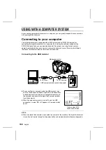
Connecting to the IEEE1394 terminal

œ

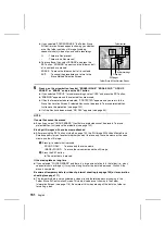
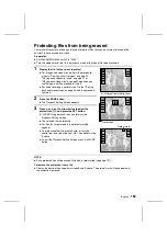
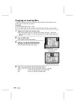
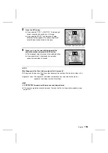
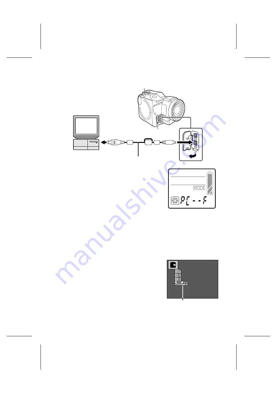
By connecting to a computer using the IEEE1394 terminal,
you can use the iD PHOTO disk drive of the digital disk
camera as an external drive of your computer. Then you
can handle the data stored in the disk from your computer.

œ

When the mode selector dial is set to 

é

 and the

IEEE1394 connection is made, “

PC--F

” appears in the

mode display panel.

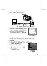
Selecting the IEEE1394 baud rate

Your digital disk camera supports communication up to 400 Mbps, but depending on the
computer to which the digital disk camera is connected, the communication may become
unstable. If this is the case, select the 

Â

 icon in the baud rate menu to restore stable

communication.

1

Turn the mode selector dial to 

ê

 to display the Option Screen.

2

Press the arrow button to select the disk icon 

â

 and press the SET button.

œ

The Disk Tools Screen appears.

3

Press 

l

 to select the baud rate menu.

4

Press 

c

 to select the desired baud rate.

Â

: Sets the baud rate to a maximum of 200 Mbps

Ê

: Sets the baud rate to a maximum of 400 Mbps

5

Press the SET button.

œ

The new baud rate is set.

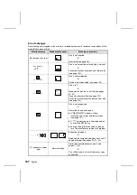
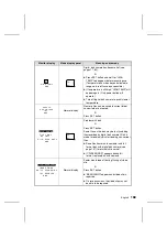
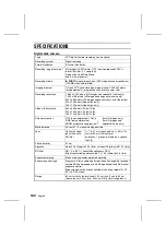
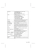
Mode selector dial

To IEEE1394 port

To IEEE1394 terminal

Interface cover

IEEE1394 computer interface cable (supplied)

Display when IEEE1394

connection is made

   DISK TOOLS
    1394 SPEED

Baud rate menu

Disk Tools Screen

English 

160

Summary of Contents for IDC-1000ZE iDshot

Page 1: ...of these products will be labeled as such Please read these instructions carefully before using the digital disk camera Make sure to read and understand the section USING YOUR DIGITAL DISK CAMERA SAFELY AND CORRECTLY from page 5 to 17 Keep this manual in a safe place for later reference Digital disk camera IDC 1000ZEX IDC 1000ZE IDC 1000ZU ...

Page 2: ...a laser The use adjustment or performance of procedures other than those specified herein may result in hazardous radiation exposure Laser Type Semiconductor laser AlGanP Output power 3 5 mW read average 5 85 mW write average Beam divergence 45 5 degrees objective lens emission Wavelength 655 to 666 nm at 20 to 25 C 1 English ...

Page 3: ... more of the following measures Reorient or relocate the receiving antenna Increase the separation between the device and receiver Connect the device to an outlet on a circuit different from that to which the receiver is connected Consult the dealer or an experienced radio television technician for help Changes or modifications not expressly approved by the party responsible for compliance could v...

Page 4: ...ot be held responsible for any problems resulting from the use of this digital disk camera œ Sanyo Electric declines all responsibility for damages due to improper use of the digital disk camera failure to adhere to the instructions given in this manual or repairs or changes done by those other than a technician authorized by the manufacturer œ Sanyo Electric shall not be held responsible for any ...

Page 5: ...K FILES ON A TELEVISION SET 71 Shooting functions USING THE VARIOUS SHOOTING FUNCTIONS 72 MANUAL MODE SETTINGS 88 Speciality shooting INTERVAL SHOOTING 98 ANIMATION SHOOTING 107 Camera settings CUSTOM SETTING 112 SETTING THE REMAINING DISK SPACE DISPLAY FORMAT 125 Editing ADDING A VOICE MEMO TO AN IMAGE 127 ADDING AN IMAGE TO ANOTHER IMAGE 130 ENLARGING ZOOMING IN THE IMAGE 134 EDITING VIDEO CLIPS...

Page 6: ...chanisms or devices dysfunctional and cause a fire rupturing of the battery pack or an eruption or leakage of electrolyte Do not short the positive and negative poles with a metal pin or other object and do not carry or store together with a metal necklace or other object œ If the poles are shorted a large amount of current will flow which may cause a fire rupturing of the battery pack eruption or...

Page 7: ...d œ When inserting the battery pack in the AC adapter charger or digital disk camera make sure the positive and negative terminals are oriented correctly as indicated œ If the battery pack is used or charged with the polarity of the terminals reversed an abnormal chemical reaction will occur during charging and an abnormal current will flow during use Both may cause a fire rupturing of the battery...

Page 8: ...echarging the battery pack will be warm This is normal and does not indicate a malfunction Take care when handling immediately after use œ The battery pack may be extremely hot immediately after use After turning off the digital disk camera allow time for the battery pack to cool before removing it Cautions concerning recycling œ To help preserve the environment and promote the effective use of re...

Page 9: ...s a danger of fire or electric shock if they are touched Also never disassemble the disk holder because the laser beam may enter your eyes and cause injury Any internal check setting or repair should be performed by the dealer Do not insert metal objects or the like œ Do not insert metal objects inside the devices or short any contacts inside the AC adapter charger Doing so may cause a fire or ele...

Page 10: ... struck by lightning do not use the digital disk camera or AC adapter charger during a thunderstorm In particular if used in an open field you have an increased chance of being struck by lightning Quickly seek refuge in a place that will protect you from lightning œ Do not touch the AC adapter charger or power cord while it is plugged into a power outlet during a thunderstorm Doing so may cause an...

Page 11: ... ignite rupturing of the batteries or other problem œ Plug only the supplied AC adapter charger into the DC IN connector on the digital disk camera Do not plug in any other device into the DC IN connector Also this AC adapter charger is for exclusive use with this digital disk camera IDC 1000ZEX IDC 1000ZE IDC 1000ZU Do not use it with any other device Use only to recharge the Sanyo UR 121 Li ion ...

Page 12: ...pplied AC adapter charger Do not use it with other devices for it may cause a fire or electric shock Unplug the power cord from the power outlet when charging is finished œ If the AC adapter charger is left plugged into the power outlet for a long period of time there is a risk of fire Do not pull on power cord to unplug it œ When unplugging the power cord be sure to hold the power plug and slowly...

Page 13: ...tc œ Places with drastic humidity and temperature changes œ Places that may get wet œ Places close to an air conditioner or heater œ Inside a car œ Places where there is dust and dirt œ Places where there is a fire burning œ Places where volatile products are stored œ Places subject to strong electromagnetic fields œ Places subject to vibrations Operating environment Digital disk camera œ Temperat...

Page 14: ...verheating or rupturing œ Do not recharge short circuit disassemble modify heat or place the battery in a fire Doing so may cause a fire overheating or rupturing œ Do not hold the battery with metal tweezers or a similar tool Doing so may cause a short circuit leading to a fire overheating or rupturing œ Do not perform soldering on the battery or use store or leave it near a fire under direct sunl...

Page 15: ... AC adapter charger Do not leave rubber or vinyl objects against the digital disk camera or AC adapter charger for a long period They may cause deformation discoloration or paint peeling Cautions when cleaning the lens œ If the lens gets dirty use a commercially available air blower or a cleaning cloth for photographic equipment to clean it œ It is also possible to clean the viewfinder see page 16...

Page 16: ...gital disk camera has reached the ambient temperature Cautions concerning undesired interference œ The digital disk camera or AC adapter charger may create undesired interference if used close to a television or radio To reduce the amount of undesired interference emitted cores are attached to the supplied AV cable and the DC cord of the AC adapter charger Do not remove these cores Also when using...

Page 17: ...r humidity œ Places subject to vibrations œ Places with drastic humidity and temperature changes œ Places with excessive static electricity or electromagnetic noise œ Do not place the iD PHOTO disk near magnets or in strong magnetic fields œ Do not disassemble the iD PHOTO disk œ Do not allow the iD PHOTO disk to get wet œ Wipe away dust or dirt with a soft dry cloth Do not use benzene thinner or ...

Page 18: ...t or corrupted in cases such as those listed below Sanyo Electric will not be held responsible for any damage or lost profits arising from the loss of data œ If the iD PHOTO disk is used incorrectly œ If the iD PHOTO disk is not inserted correctly into the digital disk camera œ If the iD PHOTO disk is subjected to electrical or mechanical shocks or other forces œ If the iD PHOTO disk is removed fr...

Page 19: ...ol pages 22 36 Lithium battery is installed at the time of purchase œ iD PHOTO disk protective case labels 730 MB DSM D730A pages 30 155 œ Protective spacer page 30 Located inside disk holder at the time of purchase Use to transport the digital disk camera œ Lens cap page 12 œ Lithium battery for clock backup CR2025 page 23 œ Core page 15 œ USB interface cable œ IEEE1394 interface cable and 3 core...

Page 20: ...N button pages 55 87 5 Microphone page 79 6 W BAL white balance button page 96 7 EXP exposure button page 92 8 FOCUS button page 90 9 Zoom switch page 74 F Lens page 14 G Remote control sensor page 36 H Self timer lamp pages 36 81 I Shutter release button pages 35 51 J Flash page 76 Press the flash pop up button to stand up the flash bulb K Flash pop up button page 76 Flash bulb Flash pop up butto...

Page 21: ... page 47 3 Grip belt holder page 48 4 Viewfinder pages 32 50 5 Monitor switch page 32 6 Arrow button page 52 7 AUTO MAN button page 89 8 Shoulder belt holder page 48 9 Terminal cover pages 29 49 71 F MIC microphone input terminal pages 49 68 G AV output terminal page 71 H DC IN external DC power input terminal page 29 I Speaker page 16 J Focus ring page 90 English 20 ...

Page 22: ... Disk holder pages 30 31 4 Interface cover page 159 5 USB terminal page 159 6 IEEE1394 terminal page 160 7 MODE button pages 43 54 8 SET button pages 43 54 9 CAMERA PLAY switch page 47 F LCD monitor pages 32 50 G Diopter adjustment lever page 33 21 English ...

Page 23: ... page 23 Remote control The page numbers listed next to the part names are the page numbers where that part is explained in detail Excluding the CH button all buttons perform the same operation as the button of the same name on the digital disk camera itself 1 Infrared emitter page 36 2 Shutter release button page 51 3 MODE button page 54 4 SET button page 54 5 Arrow button page 52 6 Battery holde...

Page 24: ...ion The backup lithium battery will last approximately one year and then will require replacement one CR2025 battery 1 Open the battery pack cover 1 Press and hold down the BATT knob on the digital disk camera bottom 2 Pull the battery pack cover toward the front of the digital disk camera and then lift it up 2 Open the clock backup battery cover and install the clock backup battery œ The clock ba...

Page 25: ...he AC adapter charger œ Insert the power cord straight and until it is fully seated 4 Plug the power cord into a power outlet AC 100 to 240 V œ Charging will start automatically œ During charging the BATTERY CHARGE lamp will light red œ Charging will take approximately 120 minutes œ When charging is completed the BATTERY CHARGE lamp will turn off NOTE œ Recharge the battery pack just before use or...

Page 26: ...umed œ During charging the battery pack and AC adapter charger will become warm This is not a malfunction If noise is received by a radio or television during charging œ Perform the charging in a location away from the radio or television Ambient temperature during charging œ The ambient temperature during charging should be kept between 10 and 35 C If the temperature drops below 10 C the characte...

Page 27: ...er charger is not connected properly œ When running the digital disk camera with the AC power supply plug one end of the power cord into power outlet and the other into the power supply socket on the AC adapter charger and plug the DC cord into the DC IN terminal on the digital disk camera The digital disk camera is not turned on œ Press the power button to turn on the digital disk camera On AC po...

Page 28: ... pack to the battery pack mating area 1 Orient the battery pack as shown in the figure below align the edges of the battery pack and the battery pack mating area and insert the battery pack in the battery pack mating area 2 Push in the direction of the arrow 3 Close the battery pack cover 1 Close the battery pack cover 2 Push it towards the back of the digital disk camera until it is secured in pl...

Page 29: ...onitor or viewfinder turn off 2 Open the battery pack cover 1 Press and hold down the BATT knob on the digital disk camera bottom 2 Pull the battery pack cover toward the front of the digital disk camera and then lift it up 3 Remove the battery pack œ Slide the battery pack toward the front of the digital disk camera and lift it upward Be careful not to drop the battery pack when removing it œ Imm...

Page 30: ...pplied power cord into the socket on the AC adapter charger œ Insert the power cord straight and until it is fully seated 2 Plug the DC cord into the DC IN terminal on the digital disk camera 3 Plug the power cord into a power outlet AC 100 to 240 V 4 Turn on the digital disk camera see page 32 œ When the digital disk camera is turned on the green AC ADAPTER lamp turns on œ If charging is being pe...

Page 31: ...t the time of purchase Remove this spacer if it is present 2 Insert the disk into the disk holder œ Insert the disk in the direction of the arrow given l mark with its label facing outwards œ Be sure to insert the disk all the way in until it is properly seated 3 Push the disk holder closed œ When the disk is inserted the disk mark in the mode display panel lights NOTE If the disk mark turns œ The...

Page 32: ...ow œ When the disk holder is opened the disk is ejected 4 Gently pull out the disk HELP If the disk cannot be removed œ If data on the disk is being accessed the disk mark is rotating see page 30 the disk holder will not open when the EJECT lever is pushed Wait until the disk mark stops rotating and the digital disk camera turns off œ If the digital disk camera is on the disk cannot be removed Tur...

Page 33: ...ess the power button for more than one second œ The digital disk camera does not turn on right away to prevent it from being turned on accidentally œ The mode display panel turns on œ The display on the viewfinder or LCD monitor turns on œ If the AC adapter charger is connected and AC power is supplied the AC ADAPTER lamp will light see page 29 Power button Mode display panel Viewfinder Monitor sw...

Page 34: ...ee page 21 To show the display in the LCD monitor move the monitor switch to MONITOR œ The display in the viewfinder turns off HELP If the timer mark in the mode display panel is flashing œ This is warning you that the date and time have not been set Once the date and time are set this mark will stop flashing see page 42 NOTE About the disk status display œ Once the power is turned on the status o...

Page 35: ...dial to select a folder number œ If an image appears press the RETURN button to exit the Skip File Screen œ If you turn the control dial and the folder number does not change then there are no other folders NOTE œ Temporary video clip interval files see page 106 and temporary animation files see page 111 are not considered video clip files and therefore the NO FILE message will appear even if they...

Page 36: ...e page 124 at the Option Screen is set to D not using remote control the digital disk camera will be turned off without going into the power save mode About the power save mode When the digital disk camera enters the power save mode SLEEP appears in the mode display panel œ The power can be turned back on with the remote control when in the power save mode œ If the power save mode is continued for...

Page 37: ...t may block the signal and prevent operation of the digital disk camera by the remote control If this is the case remove the obstruction œ Each button on the remote control performs the same operation as the button of the same name on the digital disk camera see page 22 œ When an operation is performed with the remote control the self timer lamp lights for one second to signal that the signal has ...

Page 38: ...t that time replace it only with the commercially available CR2025 lithium battery 1 Pull out the battery holder œ Push in the tab to release the battery holder and then pull it out 2 Remove the battery 3 Insert the new battery CR2025 œ Wipe the new battery with a soft dry cloth and then insert it with the mark facing upward 4 Push in the battery holder Battery holder Tab Battery mark 37 English ...

Page 39: ...cond when the remote control code changes to 2 Release the buttons on the remote control 3 Press a button on the remote control and check that the operation was carried out correctly œ The remote control code is not lost even if you replace the battery in the remote control œ If the remote control codes for the remote control and digital disk camera do not match operations will not be carried out ...

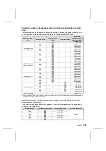
Page 40: ...isk camera to prevent problems Checking the battery pack 1 Install the battery pack see page 27 2 Turn on the digital disk camera see page 32 œ The remaining charge in the battery pack is displayed in the mode display panel œ When the battery pack becomes low on charge the remaining amount will also be displayed in the LCD monitor or viewfinder Mode display panel LCD monitor Viewfinder Mode displa...

Page 41: ... 10 C the rate the charge decreases is especially fast Therefore even the same battery pack may allow different number of images to be captured under different conditions œ Before using the digital disk camera for important situations e g wedding or when traveling or in cold environments it is recommended to take a spare battery pack with you as a precaution œ For ambient temperatures below 10 C i...

Page 42: ...of images and recording time see page 172 Display in mode display panel œ Remaining number of images remaining recording time available Depending on the current shooting mode either the remaining number of images or the remaining recording time available will be displayed œ Remaining percentage of disk space The remaining percentage of disk space available is displayed œ Remaining disk space The r...

Page 43: ... timer mark in the mode display panel will flash When the clock is set the mark will disappear see page 33 Setting the clock Preparation œ Insert a disk see page 30 œ Turn the power on see page 32 Example Setting the clock to 7 30 p m August 28 2001 1 Turn the mode selector dial to ê to display the option screen 2 Set the monitor switch to MONITOR œ The Option Screen appears in the LCD monitor 3 P...

Page 44: ...ime Select ON To not display the date and time Select OFF œ To set the date format or the date and time continue to the operations given below 5 Set the date format 1 Press c to select the date format œ The date format turns orange 2 Press j or l to select the desired date format œ Each time l is pressed the date format changes as shown below Year month day Y M D Month day year M D Y Day month yea...

Page 45: ...rrow button Decrease setting by one Press j once Increase setting by one Press l once Select the next item Press c Select the previous item Press d 7 Press the SET button œ The clock starts at the set time and you return to the Option Screen œ You can set the clock accurately by listening to an official time recording and pressing the SET button at the exact time CLOCK SET DISP OFF D M Y 2001 08 2...

Page 46: ...anged 2 Press j or l on the arrow button to change the setting to the desired value œ To change another item press d or c to select the other item and change it as desired 3 Press the SET button œ This completes the change of the date and time CLOCK SET DISP OFF D M Y 2001 08 28 19 30 CLOCK SET DISP OFF D M Y 2001 08 28 20 30 45 English ...

Page 47: ...he clock making audio recording and performing other functions Switching between the shooting and playback modes To capture images or record video clips use the shooting mode and to view images or play back video clips use the playback mode Preparation œ Insert a disk see page 30 œ Turn the power on see page 32 1 Set the CAMERA PLAY switch to CAMERA or PLAY For shooting mode Set to CAMERA For play...

Page 48: ...de Set to ê For PC connection mode Set to é Mode selector dial CAMERA PLAY switch About the modes Mode CAMERA PLAY switch Mode selector dial Shooting mode Still image shooting mode CAMERA shooting mode Sequential shot shooting mode r Video clip shooting mode 7 Playback mode Still image playback mode PLAY playback mode Sequential shot playback mode r Video clip playback mode 7 Option mode CAMERA or...

Page 49: ...oulder belt is useful for carrying the digital disk camera over your shoulder or hanging it from your neck Attaching the grip belt Attaching the shoulder belt Grip belt Adjust the length of the grip belt so your index finger can press the shutter release button Grip belt holder on digital disk camera bottom English 48 ...

Page 50: ...our elbows in toward your sides œ When using the flash see page 76 make sure that your fingers or other objects do not get in the way of the flash Using the supplied microphone In addition to the built in microphone you can also use the supplied external microphone to make audio recording when using your digital disk camera Place the microphone according to the scene that you are recording see pag...

Page 51: ...itor Using the viewfinder 1 Set the monitor switch to FINDER œ The image is displayed in the viewfinder and the LCD monitor turns off œ If the image in the viewfinder is out of focus use the diopter adjustment lever below the viewfinder to adjust it see page 21 2 Look straight into the viewfinder and center the subject Using the LCD monitor 1 Set the monitor switch to MONITOR œ The image is displa...

Page 52: ...tter sound see page 119 the set shutter sound will be heard when the shutter is released a camera clicking sound is set at the time of purchase œ You can keep the shutter release button depressed and view the captured image in the monitor œ When you release the shutter release button the clock icon appears in the monitor signifying that the image is being saved During this time images cannot be ca...

Page 53: ...ack Setting Screen step 2 on page 54 To listen to the voice memo first exit the Playback Setting Screen and then press the SET button œ To adjust the playback volume see Adjusting the volume on page 70 Useful playback features for still images Preparation œ Insert a disk see page 30 œ Turn the power on see page 32 Consecutive playback Follow the procedure below to play back images consecutively on...

Page 54: ...n reverse order saved Press j 3 To stop the automatic playback press the arrow button œ SLIDE SHOW OFF appears and automatic playback stops œ You can also press the MODE or SET buttons to stop the automatic playback NOTE œ If the Playback Setting Screen step 2 on page 54 or the Skip File Screen step 2 on page 55 appears before step 2 for automatic playback slide show then automatic playback cannot...

Page 55: ...u want to view and press the SET button œ The selected image is displayed full screen œ You can also move the mark by turning the control dial HELP If appears in the 9 image display œ may be displayed if the images were saved on the disk using a different digital disk camera If an image number is missing œ An image number is the actual file name for that image and it does not change Therefore if a...

Page 56: ...he Skip File Screen appears œ To change the folder from which to play back images press the F1 button turn the control dial to select the folder number and press the RETURN button 3 Turn the control dial to select the image number of the image that you want to view œ After a few moments the selected image is displayed full screen 4 Press the RETURN button œ The Skip File Screen disappears Mode sel...

Page 57: ...ll appear in the monitor œ When the b icon disappears from the monitor the sequential shot is finished œ When you release the shutter release button the clock icon appears in the monitor signifying that the images are being saved During this time sequential shots cannot be captured When the clock icon disappears the digital disk camera is ready to capture the next sequential shot œ To view the seq...

Page 58: ...ge of each of these sequential shot folders 2 Press the arrow button to move the mark to the sequential shot you want to view and press the SET button œ The first image of the selected sequential shot is displayed full screen œ You can also move the mark by turning the control dial HINT To quickly display a different sequential shot œ After step 2 with the Playback Setting Screen not displayed pre...

Page 59: ...he control dial HELP If appears in the 9 image display œ may be displayed if the sequential shots were saved on the disk using a different digital disk camera If a sequential shot folder number is missing œ A sequential shot folder number is the actual folder name for that sequential shot folder and it does not change Therefore if a sequential shot folder is erased see page 149 other sequential sh...

Page 60: ... and press the SET button 2 Press and hold d or c on the arrow button œ Images of the selected sequential shot are displayed one after the other while the arrow button is pressed down œ Consecutive playback in the sequential shot playback mode only displays the images for one sequential shot i e the images in one sequential shot folder NOTE To play back images from more than one sequential shot fo...

Page 61: ...o select the folder number and press the RETURN button 3 Turn the control dial to select the sequential shot folder number of the sequential shot that you want to view œ After a few moments the first image of the selected sequential shot is displayed full screen 4 Press the RETURN button œ The Skip File Screen disappears 5 Press d or c on the arrow button to view the images of the sequential shot ...

Page 62: ...ecording begins when you press the shutter release button œ While the video clip is being recorded the b icon will appear in the monitor œ By having the mode display panel show the remaining recording time available for the disk you can check the remaining amount of time available see page 125 4 Press the shutter release button again to stop recording œ Recording stops and the b icon disappears œ ...

Page 63: ...amera from becoming damaged turn it off and follow the instructions given on page 168 HELP If recording stops before the remaining available recording time expires œ After a disk has been used saving and deleting data over and over again the data stored on the disk becomes fragmented If a fragmented disk is used recording may stop before the remaining recording time available see page 41 runs out ...

Page 64: ...reen œ You can also move the mark by turning the control dial 3 Press the SET button to start the playback of the video clip œ The video clip starts audio and video The audio for the video clip can be heard from the speaker on your digital disk camera œ If the video clip was recorded at resolution N the video clip appears at 1 4 size in the middle of the monitor œ To view a different video clip pr...

Page 65: ...e the mark by turning the control dial HELP If appears in the 9 image display œ may be displayed if the video clips were saved on the disk using a different digital disk camera If a video clip number is missing œ A video clip number is the actual file name for that video clip and it does not change Therefore if a video clip is erased see page 149 other video clip numbers will not change to fill th...

Page 66: ...on 2 Press the F2 button œ The Skip File Screen appears œ At this time you can press the F1 button to change the folder from which to play back video clips To change folders after pressing the F1 button turn the control dial to select the folder number and press the RETURN button 3 Turn the control dial to select the video clip number of the video clip that you want to view œ The first frame of th...

Page 67: ... 28ths 1 Press the RETURN button œ You enter the shuttle mode and the Jog Shuttle Screen appears œ At the Jog Shuttle Screen press the F1 button to enter the jog mode and press the F2 button to enter the shuttle mode œ In the shuttle mode the video clip is divided up into 28 portions of even length and 1 28 of the video clip is skipped each time the control dial is turned one click This is useful ...

Page 68: ...ents of video clips in detail 3 Slowly turn the control dial œ The operation of the control dial and arrow button is the same as that for the shuttle mode above 4 To exit the Jog Shuttle Screen press the RETURN or SET button To adjust the volume œ Turn the mode selector dial to ê to display the Option Screen Then select the audio recording icon k and press the SET button Finally select the volume ...

Page 69: ...s the SET button œ The Audio Recording Screen appears œ The record icon z is selected initially NOTE œ Besides using the built in microphone you can also record audio by connecting the supplied microphone to the MIC input terminal Be aware that the built in microphone will not work when a microphone is connected to the MIC input terminal see page 49 Mode selector dial MIC input terminal Arrow butt...

Page 70: ...creen press the MODE button œ To return to the Option Screen from the Audio Recording Screen press the MODE button again Playing back audio recordings Preparation œ Insert a disk see page 30 œ Turn the power on see page 32 1 Put the digital disk camera in the option mode œ Turn the mode selector dial to ê to display the Option Screen 2 Press the arrow button to select the audio recording icon k 3 ...

Page 71: ...ng Press c To change to previous audio recording Press d At the Audio Recording Playback Setting Screen step 6 select the 9 image playback icon s and press the SET button œ The 9 image Playback Screen appears Perform steps 6 and 7 above To return to the beginning At the Audio Recording Playback Setting Screen step 6 select the return icon j and press the SET button œ You return to the beginning of...

Page 72: ...y them back on the digital disk camera itself œ To listen to audio recordings on the television follow the same procedure used to play them back on the digital disk camera itself œ Adjust the volume for the audio with the television controls When the AV cable is connected the volume control on the digital disk camera does not work NOTE œ The IDC 1000ZEX and IDC 1000ZE will play back images using a...

Page 73: ... l on the arrow button to select the focus menu œ The focus menu appears 3 Press c on the arrow button to select the 8 or 5 icon from the focus menu For macro focusing 3 to 60 cm Select 8 macro focus mode For macro to distant focusing 3 cm to Ö Select 5 total range focus mode For normal focusing 60 cm or greater Select 6 normal focus mode œ Although you can perform macro photography with 5 for fas...

Page 74: ... near 3 cm away it is important to move the zoom switch to T for a telescopic view 6 Press the shutter release button œ For how to focus the image see step 3 on page 51 œ The image is captured with the selected macro focus setting NOTE The difference between 5 total range focus mode and 8 macro focus mode œ 5 allows you to capture images of subjects at a distance of 3 cm or greater with autofocus ...

Page 75: ...tion Preparation œ Set the CAMERA PLAY switch to CAMERA œ Turn the mode selector dial to r or 7 to select the desired shooting mode 1 Set the zoom switch to T or W and compose the image For wide angle shooting Set to W For telescopic shooting Set to T 2 Press the shutter release button œ For how to focus the image see step 3 on page 51 HINT œ By using the optical zoom and digital zoom together you...

Page 76: ...to be used 2 Press c on the arrow button to enlarge the subject as desired œ Each time c is pressed the pointer on the zoom bar moves to the right and the subject is enlarged œ To return the subject to the original size press d The pointer moves back to the left œ The magnification provided by the digital zoom depends on the resolution as shown below Magnification Resolution P 1 to 2 1x 5 levels F...

Page 77: ...al zoom set to T Macro focus 20 cm to 60 cm Preparation œ Set the CAMERA PLAY switch to CAMERA œ Turn the mode selector dial to to select the still image shooting mode 1 Press the flash pop up button œ The flash stands up at the front of the digital disk camera œ The flash will not operate unless it has been stood up with the flash pop up button 2 Press the MODE button œ The Still Image Shooting S...

Page 78: ...he SET button œ This completes the flash mode setting œ Place the flash back in the digital disk camera to set the flash off mode 3 œ The flash mode setting is retained even if the flash is placed back in the digital disk camera the mode selector dial is turned the CAMERA PLAY switch is changed or the digital disk camera is turned off see page 112 œ By setting the desired flash mode beforehand you...

Page 79: ...tch to CAMERA œ Turn the mode selector dial to to select the still image shooting mode 1 Press the MODE button œ The Still Image Shooting Setting Screen appears 2 Press j or l on the arrow button to select the voice memo menu œ The voice memo menu appears 3 Press c on the arrow button to select the voice memo icon q To record a voice memo Select q voice memo on To not record a voice memo Select vo...

Page 80: ...ppear in the monitor œ Up to a maximum of 10 seconds can be recorded œ To stop the recording before the 10 seconds elapses press the shutter release button again œ If the shutter release button is not pressed then the maximum 10 seconds will be recorded œ Even after the recording is finished the voice memo on settings remains unchanged NOTE œ The voice memo sound file takes up approximately one ha...

Page 81: ...r menu œ The self timer menu appears 3 Press c on the arrow button to select the self timer icon v œ To set the self timer Select v self timer on œ To not set the self timer Select w self timer off 4 Press the SET button œ This completes the self timer setting œ The timer mark and the time until images are captured or recording is started appear in the mode display panel œ The default time for the...

Page 82: ...digital disk camera turns off and the self timer is stopped To turn the monitor on press the power button to turn it back off press the power button again œ You can check the time remaining before images are captured or recording starts at the mode display panel see page 80 œ To stop the self timer press the MODE button when the monitor is turned on To start the self timer again press the shutter ...

Page 83: ...A PLAY switch to CAMERA œ Turn the mode selector dial to r to select the sequential shot shooting mode 1 Press the MODE button œ The Sequential Shot Shooting Setting Screen appears 2 Press j or l on the arrow button to select the sequential shot menu œ The sequential shot menu appears Dark image under exposed Standard exposure Bright image over exposed 100 0101 Sequential Shot Shooting Setting Scr...

Page 84: ... is taken œ While the AE shift sequential shot images are being captured the b icon will appear in the monitor œ Even after the AE shift sequential shot is finished the AE shift sequential shot setting remains unchanged NOTE œ For the AE shift sequential shot even if you have set the exposure correction see page 87 the exposure correction value is returned to á0 and then the AE shift sequential sh...

Page 85: ...els Icon displayed on the LCD monitor 1360 x 1024 R 1024 x 768 Q 640 x 480 P 320 x 240 O 160 x 120 N Shooting mode Still image Yes Yes Yes No No Sequential shot Yes Yes Yes No No Video clip No No Yes Yes Yes Preparation œ Set the CAMERA PLAY switch to CAMERA œ Turn the mode selector dial to r or 7 to select the desired shooting mode 1 Press the F1 button œ The current resolution appears in the upp...

Page 86: ...mera consists of a collection of small dots The resolution refers to the number of these dots and the greater the number the higher the image quality As the resolution increases the size of the resulting data also increases and the number of images that can be captured decreases To compensate for this this digital disk camera is able to compress the data This digital disk camera uses JPEG compress...

Page 87: ...ll be converted to 15 frames second If you are going to join video clips together it is recommended to record them at the same frame rate Preparation œ Set the CAMERA PLAY switch to CAMERA œ Turn the mode selector dial to 7 to select the video clip shooting mode 1 Press the F2 button œ The current frame rate appears in the upper left hand corner of the monitor for two seconds œ The current frame r...

Page 88: ...hot mode see page 83 2 Turn the control dial to select the desired exposure correction value œ The exposure correction can be set from to 1 5 EV to 1 5 EV in 0 5 EV increments œ Select positive values for brighter images and negative values for darker images œ Set 0 EV for automatic exposure correction 3 Wait two seconds œ The exposure correction is entered and the Exposure Correction Screen disap...

Page 89: ...p shooting modes Automatic mode settings In the automatic mode the digital disk camera performs the following settings automatically œ Focus setting The focus is set automatically within the distance range of the focus mode set at the focus menu œ Exposure control setting The exposure shutter speed and aperture is set automatically according to the subject conditions Program AE œ White balance set...

Page 90: ... disk camera changes between the automatic and manual modes each time the AUTO MAN button is pressed œ In the manual mode the various settings are displayed and in the automatic mode they disappear œ Ä appears in the mode display panel in the automatic mode and Å appears in the manual mode Mode display panel Viewfinder LCD monitor AUTO MAN switch Focus setting indicator Exposure control setting in...

Page 91: ...d a focus bar appear in the monitor œ The focus bar is given as a guide When the focus bar is extended all the way to the top the focus is set appropriately for the measured distance œ When the manual focus is set the manual focus indicator appears 3 Press the RETURN button œ This completes the manual focus setting œ When the manual focus is set the focus distance indicator appears To return to au...

Page 92: ...n the control dial to select the desired focus distance 5 Press the RETURN button œ This completes the fixed focus setting œ When the fixed focus is set the focus distance indicator appears To return to autofocus select AUTO FOCUS at the Fixed Focus Screen and press the RETURN button The focus distance indicator will disappear NOTE œ If you change the focus mode see page 72 after setting the manua...

Page 93: ...ch back and forth between program AE and this locked setting œ If the EXP button is pressed while spot sample AE shutter speed priority AE aperture priority AE or manual exposure is set the Exposure Control Setting Screen in step 2 appears 2 Turn the control dial to select the desired exposure control setting œ The Exposure Control Setting Screen appears PROGRAM Program AE œ For having the digital...

Page 94: ...perture for a clear foreground and background for a deep field depth MANUAL Manual exposure œ This allows you to set a specific shutter speed and aperture as desired Example For setting a slow shutter speed when shooting in a dark location without using a flash Or for shooting nighttime scenes where lights flows across the image 3 Press the RETURN button œ When PROGRAM is not selected set the expo...

Page 95: ...appears œ Turn the control dial to select the desired aperture and press the RETURN button œ When the ND filter is activated to reduce the passage of light ND appears to the right of the aperture setting œ When the aperture priority AE is set the indicator appears When selecting MANUAL and pressing the RETURN button œ The Manual Exposure Setting Screen appears œ To set the shutter speed press the ...

Page 96: ...utter opens so the foreground people are captured and the shutter stays open for a long exposure so the dark background is also captured NOTE œ When setting a slow shutter speed it is recommended to use a tripod or other means to prevent the digital disk camera from moving œ When setting a slow shutter speed there are rare occasions when small points of light are also captured This is a characteri...

Page 97: ...o white balance and this locked setting œ If the W BAL button is pressed while sampling white balance fine sky white balance cloudy sky white balance fluorescent white balance or tungsten white balance is set the White Balance Setting Screen in step 2 appears 2 Turn the control dial œ The White Balance Setting Screen appears AUTOMATIC Auto white balance œ For having the digital disk camera automat...

Page 98: ... for when the light source is tungsten lighting œ When the tungsten white balance is set the indicator appears 3 Turn the control dial to select the desired white balance setting and press the RETURN button œ This completes the white balance setting The white balance setting indicator appears in the right side of the monitor œ If you selected SAMPLING WB after you press the RETURN button perform t...

Page 99: ... before proceeding to step 2 2 Press j or l on the arrow button to select the special shooting menu œ The special shooting menu appears 3 Press c on the arrow button to select the icon For interval shooting Select For normal shooting Select U NOTE œ By fixing the settings for still image interval shooting the images of the slow changes in the subject over time are captured more accurately If inter...

Page 100: ...tween 1 and 999 images can be captured depending on the remaining disk space and the amount of images in the folder to which you are saving see page 148 6 Press the SET button œ The Still Image Interval Shooting Ready Screen appears œ To stop the interval shooting before it is completed press the MODE button œ The timer mark and the time until the next image is captured hrs min sec appear in the m...

Page 101: ...he interval shooting 3 Press the SET button œ If you selected CONTINUE the interval shooting resumes œ If you selected STOP the interval shooting is ended and you return to the Still Image Shooting Setting Screen step 1 HELP If ERROR is displayed when the power is turned on œ If the interval shooting was not completed properly due to a reason such as the battery power running out this error messag...

Page 102: ...rrow button to select the icon For interval shooting Select For normal shooting Select U For animation shooting Select T NOTE œ By fixing the settings for video clip interval shooting the images of the slow changes in the subject over time are captured more accurately If interval shooting is performed with the digital disk camera set to autofocus program AE and auto white balance then each image m...

Page 103: ... data for a video clip interval shooting or animation shooting see page 107 already exists in the digital disk camera Either save the temporary data or erase it see steps 2 and 3 on page 105 To start a new video clip interval shooting you will need to erase any existing temporary data If ERROR is displayed when the power is turned on œ If the interval shooting was not completed properly due to a r...

Page 104: ...t is completed press the MODE button œ The timer mark and the time until the next image is captured hrs min sec appear in the mode display panel INTERVAL MOV READY INT 0 00 20 DUR 0 00 05 00 Video Clip Interval Shooting Ready Screen Timer mark Time until next frame is recorded hrs min sec Mode display panel 103 English ...

Page 105: ...at is completed the Video Clip Shooting Setting Screen appears œ If the interval shooting is completed while the monitor is turned off the video clip is not created and the digital disk camera automatically turns off Afterward be sure to create the video clip with the captured images see page 106 œ The digital disk camera cannot be turned off during interval shooting You will need to first end the...

Page 106: ...temporary data is used to create a video clip When this is completed the video clip interval shooting is ended œ If you selected DISCARD DATA the temporary data is erased See step 2 on page 106 œ If you selected EXIT the interval shooting is stopped with the images captured stored as temporary data In this condition you can perform all of the functions of the digital disk camera except for video c...

Page 107: ...t BUILD MOVIE and press the SET button 2 Press j on the arrow button to select YES and press the SET button œ ERASING appears œ When the erasing is completed the Video Clip Shooting Setting Screen appears NOTE œ Even after the temporary data is used to create a video clip it still remains and is not erased Your digital disk camera is programmed to not automatically erase the temporary data œ Since...

Page 108: ...ettings cannot be changed in the middle of animation shooting If necessary change these settings as desired before proceeding to step 2 2 Press j or l on the arrow button to select the special shooting menu œ The special shooting menu appears 3 Press c on the arrow button to select the T icon For animation shooting Select T For normal shooting Select U For interval shooting Select NOTE œ By fixing...

Page 109: ...ess the power button To turn it back off press the power button again œ The recording time until now and number of frames displayed in the monitor will change as shown below Frame rate is set to X Increases one frame at a time Frame rate is set to W Increases two frames at a time œ The maximum number of frames that can be captured can be up to 999 frames depending on the remaining disk space ANIMA...

Page 110: ...it see 2 and 3 of step 7 on page 110 To start a new animation shooting you will need to erase any existing temporary data NOTE œ When performing animation shooting if necessary use a tripod and the remote control to capture images This prevents the digital disk camera from moving and ensures the same camera angle ANIMATION ERROR DATA EXIST ÄBUILD MOVIE DISCARD DATA EXIT ANM 30FPS DUR 0 00 00 00 An...

Page 111: ...111 œ If you selected EXIT the animation shooting is stopped with the images captured stored as temporary data In this condition you can perform all of the functions of the digital disk camera except for animation shooting and video clip interval shooting see page 101 If you attempt to perform animation shooting the Animation Shooting Error Screen see page 109 will appear and if you attempt to per...

Page 112: ...MOVIE and press the SET button 2 Press j on the arrow button to select YES and press the SET button œ ERASING appears œ When the erasing is completed the Video Clip Shooting Setting Screen appears NOTE œ Even after the temporary data is used to create a video clip it still remains and is not erased Your digital disk camera is programmed to not automatically erase the temporary data œ Since the tem...

Page 113: ... to ê to display the Option Screen 1 Press the arrow button to select the camera icon ò and press the SET button œ The Camera Setting Screen appears 2 Press j or l on the arrow button to select the hold settings menu œ The hold settings menu appears 3 Press c on the arrow button to select d or c To store settings even after turned off Select d To return to initial settings after turned off Select ...

Page 114: ...oper settings by following the procedure below Preparation œ Turn the mode selector dial to ê to display the Option Screen 1 Press the arrow button to select the camera icon ò and press the SET button œ The Camera Setting Screen appears 2 Press j or l on the arrow button to select the exposure metering menu œ The exposure metering menu appears 3 Press c on the arrow button to select B or J For mat...

Page 115: ...button to select the ISO menu œ The ISO menu appears 3 Press c on the arrow button to select the desired ISO sensitivity S For having the ISO sensitivity set automatically between ISO 100 and 200 equivalency K Sets the sensitivity equivalent to ISO 100 L Sets the sensitivity equivalent to ISO 200 M Sets the sensitivity equivalent to ISO 400 4 Press the SET button œ This completes the ISO sensitivi...

Page 116: ...on and also move files from one folder to another By creating folders your files can be neatly organized when they become too many to commit to memory Creating a folder Preparation œ Turn the mode selector dial to ê to display the Option Screen 1 Press the arrow button to select the camera icon ò and press the SET button œ The Camera Setting Screen appears 2 Select the folder icon and press the SE...

Page 117: ...e page 118 and press the SET button œ Change folders at the Skip File Screen see pages 55 60 65 œ If you turn off the digital disk camera while it is in a playback mode and then turn it back on a file from the previously selected playback folder will be displayed If you perform any shooting those files will be saved to the save folder selected at the Folder Setting Screen At this time if you retur...

Page 118: ...he desired folder and press the SET button œ This sets to which folder subsequent files are saved the save folder œ You return to the Camera Setting Screen NOTE œ Changing the playback folder is performed at the Skip File Screen see pages 55 60 65 or Folder Information Screen see page 118 The save folder can only be changed at the Folder Setting Screen shown above Option Screen OPTIONAL FUNCTIONS ...

Page 119: ...e playback folder NOTE œ The playback folder can also be changed at the Skip File Screen see pages 55 60 65 The save folder is changed at the Folder Setting Screen see page 117 œ Up to 900 folders folder numbers 100 to 999 can be created on one disk œ Temporary video clip interval shooting data see page 106 and temporary animation shooting data see page 111 are not video clips and will not show up...

Page 120: ... Screen appears 2 Press j or l on the arrow button to select the shutter sound menu œ The shutter sound menu appears 3 Press c on the arrow button to select H or I and press the SET button To play the shutter sound Select H To not play the shutter sound Select I To change the shutter sound see next page Select A œ This completes the setting of whether or not to play the shutter sound œ Even if H i...

Page 121: ...ton to select the shutter sound menu œ The shutter sound menu appears 3 Press c on the arrow button to select A and press the SET button œ The Shutter Sound Screen appears MIC To record a sound using the microphone FILE To use a stored audio recording DEFAULT To return to the initial setting œ You can press the shutter release button to hear the currently selected shutter sound œ MIC is selected i...

Page 122: ...til when the image is captured will become longer œ In addition to recordings made using the microphone you can also use the software included in the SANYO Software Pack to set sound files saved in your computer œ Any silent portions at the beginning or end of the sound file will be cut and not used as the shutter sound provided there is no background noise In the example below only the portion wi...

Page 123: ...s the arrow button to select the camera icon ò and press the SET button œ The Camera Setting Screen appears 2 Press j or l on the arrow button to select the shutter sound menu œ The shutter sound menu appears 3 Press c on the arrow button to select A and press the SET button œ The Shutter Sound Screen appears Option Screen OPTIONAL FUNCTIONS Camera Setting Screen Shutter sound menu PREFERENCES OP ...

Page 124: ...œ For normally recorded audio recordings see page 68 only the first five seconds are used for the shutter sound œ You can press the shutter release button to hear the currently selected shutter sound œ To return to the Option Screen press the MODE button NOTE œ To return the shutter sound to its initial setting select DEFAULT at the Shutter Sound Screen and press the SET button PREFERENCES OP SOUN...

Page 125: ...E To not use the remote control Select D 4 Press the SET button œ This completes the setting of whether or not you will use the remote control œ Refer to page 36 for information regarding the use of the remote control œ To return to the Option Screen press the MODE button NOTE œ The power save function see page 35 will differ depending on the remote control menu setting E If the digital disk camer...

Page 126: ... button œ The Disk Tools Screen appears œ The remaining disk space display format menu is selected initially 2 Press c on the arrow button to select the desired remaining disk space display format œ Select the format to use for displaying the remaining disk space To display the remaining number of images remaining recording time available Select x To display the remaining percentage of disk space ...

Page 127: ... shot shooting Remaining recording time video clip shooting Remaining percentage Remaining disk space NOTE Even after formatting the remaining disk space will not be 730 megabytes or 100 œ An iD PHOTO disk has 356 832 sectors of 2 048 bytes each for a total capacity of 730 791 936 bytes However the digital disk camera calculates one megabyte as 1 048 574 bytes for the display of the remaining disk...

Page 128: ...e MODE button to display the Playback Setting Screen 3 Press j or l on the arrow button to select the edit still image icon o 4 Press the SET button œ The Edit Image Screen appears œ At this time you can still press d or c or turn the control dial to select another image NOTE œ If an image is protected you cannot add a voice memo To add a voice memo first remove the protection see page 152 and the...

Page 129: ...rn to the Edit Image Screen œ To record voice memos for other images press d or c or turn the control dial to select the desired image and repeat steps 5 and 6 œ To return to the Playback Setting Screen press the MODE button or select EXIT and press the SET button œ For images with a voice memo the voice memo mark n will appear in the Playback Setting Screen œ To listen to the voice memo press the...

Page 130: ...new voice memo will replace the previous one œ Besides using the built in microphone you can also record the voice memo by connecting the supplied microphone to the MIC input terminal Be aware that the built in microphone will not work when a microphone is connected to the MIC input terminal see page 49 HELP If DISK FULL appears œ This indicates that there is not enough empty space on the disk to ...

Page 131: ...isting of an image within an image This function can be used for simple image editing such as adding a picture of a face to a name card Compound image creation process 1 Display the image for the background 2 Set the size of the image to be added 3 Set the position of the image to added 4 Capture the image to be inserted press the shutter release button œ The compound image is created œ The origin...

Page 132: ...till image playback mode Display the image for the background 1 Display the still image for the background 2 Press the MODE button to display the Playback Setting Screen 3 Press j or l on the arrow button to select the edit still image icon o and press the SET button œ The Edit Image Screen appears œ ADD PHOTO is selected initially 4 Press the SET button œ The guidelines to set the frame for the i...

Page 133: ...T button œ The first point is set where the guidelines intersect œ The guidelines for setting the second point appear 7 Use the arrow button to set the second point and press the SET button œ The size of the frame is now set by the rectangle formed by the two selected points To set the size of the frame first set the top left corner of the frame first point and then the bottom right corner of the ...

Page 134: ...still image œ To return to the Playback Setting Screen press the MODE button or select EXIT and press the SET button HELP If DISK FULL appears œ This indicates that there is not enough empty space on the disk to save the compound image An amount of free space equal to the size of the background image is required If you wish to save the image you must first erase some data in order to free up some ...

Page 135: ...on 4 To further enlarge the image press the SET button again œ Each time the SET button is pressed the image is enlarged œ You can also turn the control dial to perform the same operation To enlarge Turn clockwise To return to original size Turn counter clockwise œ The maximum amount an image can be enlarged will depend on its resolution R resolution Up to 7 magnifications Q resolution Up to 6 mag...

Page 136: ... back while enlarged œ For R resolution the maximum magnification amount is 21x HELP If DISK FULL appears when you try to save the magnified image œ This indicates that there is not enough empty space on the disk to save the image If you wish to save the image you must first erase some data in order to free up some space see page 149 135 English ...

Page 137: ...ther and save them as one separate clip 1 Display the video clip to become the first portion 2 Select the video clip to be last portion 3 Join the video clips press the SET button œ The video clips are joined and saved as a new video clip œ The original video clips can be left untouched The original video clips can be erased at this step NOTE Concerning video clip editing œ Do not turn off the dig...

Page 138: ...ill be saved whether the beginning or ending portion will include the selected scene 3 Press the MODE button to display the Playback Setting Screen 4 Press j or l on the arrow button to select the edit video clip icon i and press the SET button œ The Edit Video Clip Screen appears œ CLIPPING is selected initially Beginning portion Ending portion Video clip start Selected scene Video clip end 28 08...

Page 139: ...ion is saved œ To return to the Playback Setting Screen press the MODE button or select EXIT and press the SET button HELP If DISK FULL appears œ This indicates that there is not enough available space on the disk to save the new video clip For more information refer to Concerning video clip editing on page 136 If BATTERY EMPTY appears œ Video clip editing cannot be performed because the remaining...

Page 140: ...utton to display the Playback Setting Screen 3 Press j or l on the arrow button to select the edit video clip icon i and press the SET button œ The Edit Video Clip Screen appears 4 Press l on the arrow button to select JOINT 5 Press the SET button œ The 9 image Playback Screen for video clips appears Video clip displayed now Video clip to be attached Video clip start Video clip end 28 08 2 28 08 2...

Page 141: ...p editing on page 136 If SIZE ERROR appears œ If the resolutions of the video clips are different they cannot be joined To join video clips together select video clips recorded in the same resolution If BATTERY EMPTY appears œ Video clip editing cannot be performed because the remaining charge in the battery pack is too low Recharge the battery pack replace it with a charged battery pack or connec...

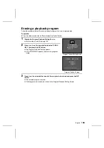
Page 142: ...on Screen Caution œ Before creating a program be sure to move the write protect tab on the disk to the write enabled position If the tab is set to the write protect position the è mark the program cannot be saved and the programmed playback cannot be performed 1 Press the arrow button to select the program playback icon ù and press the SET button œ The Program Playback Selection Screen appears To ...

Page 143: ... of the type selected 7 Select the files in the order you want them to be played back 1 Press the arrow button to move the mark to the desired file 2 Press the SET button œ A check mark is placed on the selected file œ To erase the check mark press the SET button again œ To change folders or type of file press the MODE button to display the Compile Program Screen and repeat steps 4 to 6 œ Repeat 1...

Page 144: ...0Press the SET button œ The Compile Program Screen appears The program has been compiled and saved œ To return to the Program Playback Setting Screen press the MODE button To then return to the Program Playback Selection Screen press the MODE button again or select EXIT and press the SET button To then return further back to the Playback Setting Screen press the MODE button or select EXIT and pres...

Page 145: ...and press the SET button œ The Program Playback Selection Screen appears To return to the Option Screen Select EXIT To create a playback program Select VIEWER 2 Press l on the arrow button to select VIEWER and press the SET button œ The Program Playback Setting Screen appears Program playback icon Option Screen OPTIONAL FUNCTIONS Program Playback Selection Screen SPECIAL FUNCTION EXIT ÄVIEWER Prog...

Page 146: ... arrow button to select the desired program number and press the SET button œ The playback program is selected and playback begins œ To stop the playback press the MODE button œ When playback is completed you return to the Program Playback Selection Screen Program Selection Screen PLAYBACK Ä0001 0002 0003 23 08 2001 19 00 0001 145 English ...

Page 147: ... button to select PROG DEL and press the SET button œ The Program Deletion Screen appears œ If NO PROGRAM appears there are no programs stored 3 Press l on the arrow button to select the program to be erased and press the SET button œ The selected program is erased œ If all programs are erased you return to the Program Playback Setting Screen Program Playback Setting Screen PROGRAM PLAYBACK ÄPROG ...

Page 148: ...es You can receive high quality printouts of the images you capture Caution To print out a single shot from a sequential shot or a single scene from a video clip you may need to first copy the data as a still image see page 153 Be aware that if the image resolution is low depending on the print size the output image may not be high quality Data file formats The format of the files saved on the dis...

Page 149: ... supplied œ To view images using MediaPlayer on a computer running Windows use the software included in the SANYO Software Pack supplied to change the images to the Windows compatible AVI format 100SANYO 101SANYO SANY0001 jpg SANY0002 tif SANY0003 jpg Still image file SANY0003 wav Voice memo file SEQT0001 SEQT0101 jpg SEQT0102 jpg Sequential shot folder number see page 57 ROOT Files will be stored...

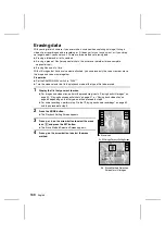
Page 150: ...k mode of the type of file to be erased 1 Display the file that you want to erase œ For images and video clips perform the procedure given in Playing back still images on page 52 Playing back sequential shots on page 57 or Playing back video clips on page 63 depending on the file type and then proceed to step 2 œ For audio recordings perform step 1 to 6 of Playing back audio recordings on page 69 ...

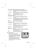
Page 151: ...folder and all of its contents All still images sequential shots video clips and audio recordings inside the folder will be erased GROUP ERASE Erases all the video clips inside the current folder Still images sequential shots and audio recording will not be erased Files inside other folders will not be erased ONE ERASE Erases the video clip currently being displayed EXIT Returns you to the Playbac...

Page 152: ...protected cannot be erased To erase protected files first remove the protection see page 152 Erasing still images with a voice memo attached œ After pressing the SET button at step 5 on page 150 the Still Image With Voice Memo Erase Screen appears for you to select whether you want to erase only the voice memo or the voice memo and the still image 1 Press j to select what is erased SOUND ONLY To e...

Page 153: ...tep 3 2 Press the MODE button œ The Playback Setting Screen appears 3 Press j or l on the arrow button to select the protect icon e and press the SET button œ LOCKED appears and then you return to the Playback Setting Screen œ The selected file is protected œ For files that are protected the protect mark ö appears œ To protect another file press d or c or turn the control dial and select the next ...

Page 154: ...7 or Playing back video clips on page 63 depending on the file type 2 Press the MODE button œ The Playback Setting Screen appears 3 Press j or l on the arrow button to select the copy move icon â and press the SET button œ The Copy Move Selection Screen appears 4 Press l on the arrow button to select the desired function COPY Ü PHOTO G To copy and save the displayed image as a still image MOVE To ...

Page 155: ...hot is displayed the complete sequential shot folder is moved NOTE What happens to the file or folder number after it is moved Still images and video clips The file number becomes the number after the last number in the folder Sequential shots The sequential shot folder number becomes the number after the last sequential shot folder number in the folder HELP If PROTECTED appears and the move canno...

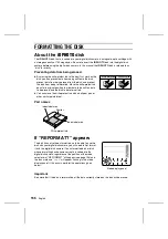
Page 156: ...en data to be erased and the disk to be reformatted œ You can move the write protect tab with a ballpoint pen or other similar pointed tool Part names If REFORMAT appears The disk has not yet been formatted so to be able to use the disk with your digital disk camera you will need to first format it with the digital disk camera If an unformatted disk or disk whose formatting has become corrupt is i...

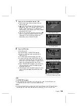
Page 157: ... press the MODE button after the status bar appears If you cancel the format be sure to properly format the disk later œ When FORMATTING disappears and you return to the normal operation screen formatting has been completed successfully œ If formatting cannot be completed properly for a disk the disk may be damaged Replace the disk with a new one HELP If PROTECTED appears œ The write protect tab o...

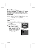
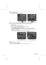
Page 158: ...ended to perform a full format beforehand Important Be aware that if the disk is reformatted all the data currently stored on the disk even protect data see page 152 will be erased Preparation œ Insert a disk with its write protect tab set to the write enabled position see page 155 œ Turn the mode selector dial to ê to display the Option Screen 1 Press the arrow button to select the disk icon â an...

Page 159: ...the disk later œ When formatting is completed you return to the Disk Tools Screen HELP If FORMAT FAILED and û appear œ Format was not completed properly Press the SET button and try again Format Confirmation Screen when the quick format icon XXX was selected DISK TOOLS QUICKFORMAT ERASE ALL YES ÄNO DISK TOOLS FULL FORMAT ERASE ALL YES ÄNO AC ADAPTER REQUIRED Format Confirmation Screen when the ful...

Page 160: ...for the interface is required Connecting to the USB terminal œ By connecting to a computer using the USB terminal you can use the software included in the SANYO Software Pack to download data from the disk in the digital disk camera to the computer and operate the digital disk camera remotely from the computer œ When the mode selector dial is set to é and the USB connection is made PC U appears in...

Page 161: ...d the communication may become unstable If this is the case select the  icon in the baud rate menu to restore stable communication 1 Turn the mode selector dial to ê to display the Option Screen 2 Press the arrow button to select the disk icon â and press the SET button œ The Disk Tools Screen appears 3 Press l to select the baud rate menu 4 Press c to select the desired baud rate  Sets the baud...

Page 162: ...a The accessories available for your digital disk camera are given below œ Li ion battery pack part number UR 121AEX UR 121A One Li ion battery pack UR 121 œ iD PHOTO disk part number DSM D730ACEX DSM D730ACU One 730 megabyte iD PHOTO disk DSM D730A 161 English ...

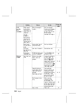
Page 163: ...ket to warm it up before using 39 Shooting Shutter release button does not work Power is not turned on If power save function has activated press shutter release button or power button once and then perform shooting 35 Clock icon appears ready status Wait until clock icon disappears 51 Disk is full DISK FULL appears in monitor and REMAIN 0 appears in mode display panel Replace with a new disk 30 3...

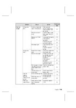
Page 164: ...switch is set to CAMERA Turn CAMERA PLAY switch to PLAY 46 Viewing images Focus does not work Subject is too close If subject is between 3 to 60 cm away set focus to 8 macro focus or 5 total range focus if subject is farther than 60 cm away set focus to 6 normal focus or 5 total range focus 72 90 Focus is not set properly Digital disk camera moved when shutter release button was pressed Hold digit...

Page 165: ...is being used Set to flash mode other than forced flash 76 Subject is too bright Change camera angle or use other means to decrease subject brightness Use exposure correction 87 Capture using spot sample AE setting 93 Shutter speed is slower than proper value for shutter speed priority AE Adjust shutter speed to proper value 94 ISO sensitivity is not set correctly Set ISO sensitivity to proper val...

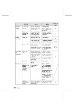
Page 166: ...rom being recorded use supplied external microphone 49 61 68 79 Connecting to television No sound or image Digital disk camera is not properly connected to television AV cable is connected to MIC input etc Connect properly connect AV cable to AV output terminal on digital disk camera 71 Television input is not set correctly Set input to VIDEO No sound Volume of television is too low Adjust volume ...

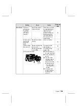
Page 167: ...uring power save mode Sounds from internal circuitry Not a malfunction 35 Remote control does not work Remote control codes do not match Set remote control codes properly 38 Remote control mode is set to D Set remote control mode to E 124 Dust is inside viewfinder 1 Remove screws 2 on side of viewfinder 14 2 Pull out and remove eyecup 3 Clean dust from inside eyecup and viewfinder with a blower or...

Page 168: ...ges 30 31 Erase unnecessary files see page 149 Save files to other media and erase from disk see page 159 Disk is not recognized Remove disk and insert again œ If REFORMAT appears follow instructions on screen and reformat disk see page 157 œ If appears again either replace disk or press the SET button œ Leaving the digital disk camera turned on for a few minutes may remedy the problem Battery pac...

Page 169: ...lem with disk Press SET button Some files on the disk may be lost including files recorded by digital disk camera Disk is made to read only disk for reading non corrupt files œ Save files from disk to computer and full format disk with digital disk camera see page 157 to return disk to normal œ If DISK ERROR appears during full format replace disk with new one Normal display Power was turned off d...

Page 170: ...320 x 240 pixels 30 fps 15 fps 160 x 120 pixels 30 fps 15 fps Data compression TIFF non compressed YCbCr for still images only FINE low compression for still images and NORM moderate compression sequential shots only White balance Full auto TTL manual setting possible Lens Optical 3x zoom lens with built in ND filter f 7 to 21 mm equivalent to f 38 to 114 mm for 35 mm film camera autofocus 7 group...

Page 171: ... m normal focus lens wide 0 6 to 1 5 m normal focus lens tele 0 2 to 0 6 m macro focus guide number 6 8 Flash modes Automatic flash mode forced flash mode slow synchronic shooting possible red eye reduction flash mode flash off mode Focus TTL type AF TTL contrast detection method manual focus fixed focus Self timer 10 second delay initial setting can be set up to 9 hours 59 minutes 59 seconds Spec...

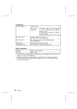
Page 172: ... supplied AC adapter charger NC LSC04WSA only USB terminal USB port supports cam control mode IEEE1394 terminal IEEE1394 port 4P supports disk drive mode Battery operation Shooting Approx 1 hour 30 minutes Playback Approx 2 hours œ Until batteries run out when using the supplied disk and the supplied Li ion battery pack at full charge at a 20 C ambient temperature œ The time of operation may vary ...

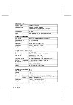
Page 173: ...s U 2300 images P Y 1000 images Z 3000 images U 5000 images Sequential shot mode R Z 1200 images U 2000 images Q Z 2000 images U 3000 images P Z 4800 images U 12000 images Video clip mode P X 8 minutes W 16 minutes O X 20 minutes W 40 minutes N X 60 minutes W 120 minutes Audio recording 2 hours x 12 œ Even with disks of the same capacity the amount of data that can actually be stored may differ de...

Page 174: ...ower supply AC 100 to 240 V 26 to 36 VA 50 to 60 Hz Rated output DC 8 4 V 0 to 1 1 A charging DC 9 2 V 0 to 1 2 A DC output Compatible battery Supplied or sold separately Li ion battery pack UR 121 Ambient environment Temperature 0 to 35 C operation 20 to 60 C storage Humidity 45 to 85 no condensation Dimensions 55 W x 38 5 H x 120 D mm Weight Approx 190 g without power cord Supplied Li ion batter...

Page 175: ...http www idshot com en SANYO Electric Co Ltd Printed in Japan ...

Reviews: