


MAX100/200-OPERATION Rev200813
69
This calibration need to be performed first before any injector foam flow meters calibrations are done. Master Foam
Flowmeter will be used as reference device for injector foam flow meters calibrations.
To perform this calibration the operator needs to:
1. Make sure all display modules are showing the "OFF" state
2. Select the discharge equipped with the foam injector and corresponding display module. It is recommended to
select the larger size discharge for this process, if possible.
3. Locate foam calibration valve associated with injector connected to an external volume meter to calibration
valve (
if the installation has a foam calibration manifold attached to an external volume meter to discharge
side of manifold
).
4. Connect the return hose to safely discharge liquid or to return it to the foam supply line or foam tank.
5. Turn the calibration valve in the ‘Calibration’ position. Flow will now be directed out of the injector assembly
through an external volume meter.
6. Make sure the hydraulic system is running and PTO is engaged.
7. Using this discharge display module, the open main menu.
8. In the main menu, select the MAINTENANCE item by pressing
INCREASE
or
DECREASE
buttons. Press
the
SELECT
button to access the submenu.
9. In the MAINTENANCE submenu select the 'FOAM CAL. MASTER' item using the
INCREASE
or
DECREASE
button. Press the
SELECT
button to start the Master foam flow calibration process.
10. Warning dialog box will be displayed; press
SELECT
button to continue.
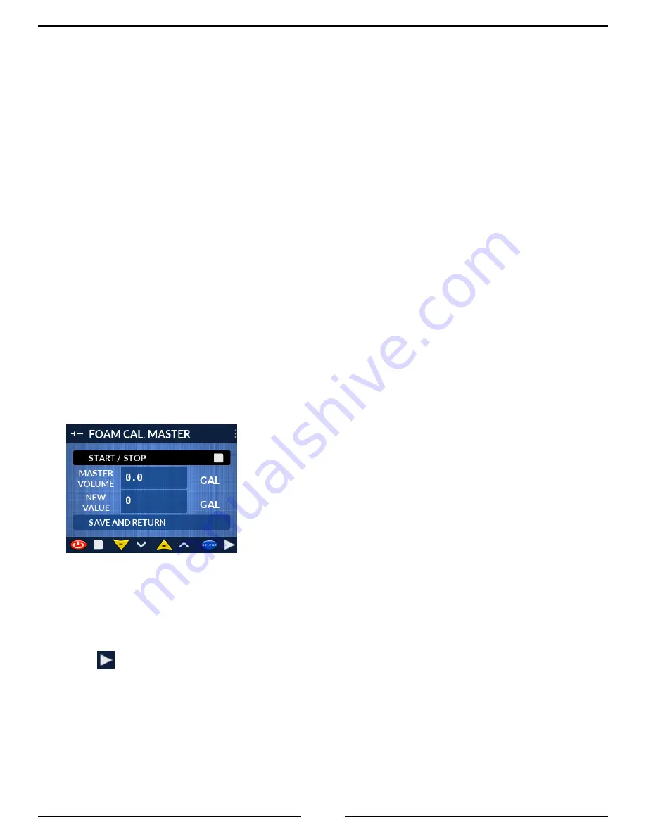
11. Calibration screen will open:
12. Reset the external volume meter to read 0. Make sure the unit of measure for the reference meter matches the
unit of measure displayed on the screen.
13. ‘START / STOP’ item should be selected on the screen. If it is not, then use the
INCREASE
or
DECREASE
button to select it.
14. Press the
SELECT
button to start measured flow. Icon on the right side of ‘START / STOP’ item should change
to
indicating system is getting ready to run. After several seconds, the foam pump will engage and flow will
be observed.
15. Once flow starts, set the back-pressure in the line to approx. 50 psi/340 kPa/3.4 BAR. If using calibration kit
3430-0381, this can be achieved by partially closing the valve provided in the assembly until the gauge reading
reaches the desired back-pressure.
16. Let the system run until a substantial volume has been accumulated. The larger the volume, the more accurate
the calibration will be. If needed, the flow can be stopped and resumed using respectively
SELECT
and
ON/
OFF
buttons. Each time flow is stopped or resumed icon on the right side of ‘START / STOP’ item will indicate
so. Note it may take up to 15s to stop or resume flow.