


64
TX11 June 2011
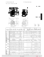
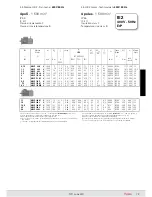
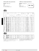
Dimensioni principali di accoppiamento delle forme costruttive
con flangia
Main mating dimensions of the mounting positions with flange
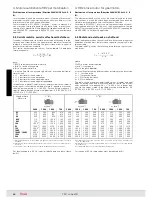
Carcassa
di lega leggera pressofusa;
forma costruttiva IM B3 con piedi
riportati e, per grand. 90 ... 200, mon-
tabili su
tre lati
.
Scudo lato comando
(
o flangia
) e
lato opposto comando
di ghi sa o
di lega leggera (ved. tabella sottori-
portata).
Scudi e flange con
attacchi di serrag-
gio «in appoggio»
e montati sulla car-
cassa con accoppiamento «
stretto
».
Cuscinetti volventi a sfere
(ved.
tabella sottoriportata) lubrificati «a
vita» in assenza di inquinamento
dall’esterno; molla di precarico.
Housing
in pressure diecast light
alloy; mounting position IM B3 with
inserted feet which, for sizes 90 ...
200 can be mounted on
three sides
.
Drive end
(
or flange
) and
non-drive
end endshield
in cast iron or light
alloy (see table below).
«Supported» tightening attach-
ments
of endshields and flanges
fitted on housing with «
tight
» cou-
pling.
Ball bearings
(see table below) lubri-
cated «for life» assuming pollu tion-
free surroundings; preload spring.
LL = lega leggera G = ghisa
1) Di ghisa per IM B14 e IM B5
derivate.
2) Di ghisa per IM B5.
LL = light alloy G = cast iron
1) In cast iron for IM B14 and IM B5
derivatives.
2) In cast iron for IM B5.
Grand. motore
Motor size
Materiale scudi e cuscinetti
Endshield material and bearings
lato comando
drive end
lato opp. comando
non-drive end
63
LL 6202 2Z
6202 2RS LL
71
LL 6203 2Z
6203 2RS LL
80
LL 6204 2Z
6204 2RS LL
90
LL 6205 2Z
6205 2RS LL
100
LL 6206 2Z
6206 2RS LL
112
LL 6306 2Z
6306 2RS LL
132
LL
1)
6308 2Z
6308 2RS G
160S
G 6309 2Z
6308 2RS G
160M ... 180M
LL
2)
6310 ZC3
6309 2ZC3 G
180L
G 6310 ZC3
6310 2ZC3 G
200
G 6312 ZC3
6310 2ZC3 G
Forma
costruttiva
Mounting
position
Estremità d’albero Ø D x E – Flangia Ø P
Shaft end Ø D x E – Flange Ø P
Grandezza motore - Motor size
IM
63
71
80
90
100, 112
132
160
180
200
11 × 23
140
14 × 30
160
19 × 40
200
24 × 50
200
28 × 60
250
38 × 80
300
42 × 110
350
48 × 110
350
55 × 110
400
9 × 20
120
11 × 23
140
14 × 30
160
19 × 40
200
24 × 50
200
28 × 60
250
38 × 80
300
3)
−
48 × 110
350
−
−
−
−
19 × 40
200
1)
24 × 50
200
2)
−
−
−
11 × 23
120
14 × 30
140
19 × 40
160
−
28 × 60
200
38 × 80
250
−
−
−
−
11 × 23
120
14 × 30
140
19 × 40
160
−
−
−
−
−
−
−
−
−
19 × 40
160
1)
−
−
−
−
11 × 23
90
14 × 30
105
19 × 40
120
24 × 50
140
28 × 60
160
38 × 80
200
−
−
−
−
11 × 23
90
14 × 30
105
−
−
−
−
−
−
1) Forma costruttiva a richiesta.
2) Il motore può funzionare anche nelle forme costruttive IM B6, IM B7 e IM B8; in targa
rimane indicata la forma costruttiva IM B3.
1) Mounting position on request.
2) Motor can also operate in the mounting positions IM B6, IM B7 and IM B8; the name
plate shows the IM B3 mounting position.
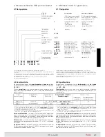
IM
B3
2)
IM
V5
IM
V6
IM
B5
IM
V1
IM
V3
IM
B14
IM
V18
IM
V19
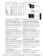
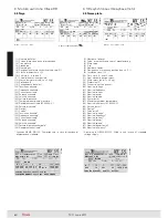
Forme costruttive IM B5, IM B3
1)
IM B14
1)
; i motori possono funzionare
anche nelle corrispondenti forme costruttive ad asse verticale, rispet-
tivamente (ved. tabella seguente): IM V1 e IM V3, IM V18 e IM V19, IM V5
e IM V6; in targa rimane comunque indicata la designazione della forma
costruttiva ad asse orizzontale escluso il caso di motori con fori scarico
condensa, ved. cap. 4.7.(8). A richiesta, altre forme costruttive speciale:
interpellarci.
Mounting positions IM B5, IM B3
1)
IM B14
1)
; motors can also ope-
rate in the relevant mounting positions with vertical shaft, which
are respectively (see following table): IM V1 and IM V3, IM V18 and
IM V19, IM V5 and IM V6; the name plate shows the designation
of mounting position with horizontal shaft excluding motors having
condensate drain holes, see ch. 4.7.(8). On request, other special
mounting positions: consult us.
1) Forma costruttiva non disponibile per motore 112.
2) Forma costruttiva non disponibile per motore 132MA ... MC.
3) Forma costruttiva non disponibile per motore 160S.
1) Mounting position not available for motor 112.
2) Mounting position not available for motor 132MA ... MC.
3) Mounting position not available for motor 160S.
Forme costruttive con flangia - Mounting positions with flange
Forme costruttive con piedi - Mounting positions with feet
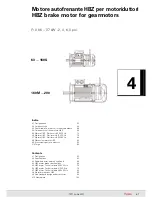
4. Motore autofrenante HBZ per motoriduttori
4. HBZ brake motor for gearmotors
Summary of Contents for TX11 Series
Page 2: ......
Page 203: ...203 TX11 June 2011...