


24
TX11 June 2011
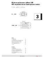
3. Motore asincrono trifase HB
3. HB asynchronous three-phase motor
sulla carcassa con accoppiamento
«stretto».
Cuscinetti volventi a sfere
(ved.
ta bella a lato) lubrificati «a vita» in
assen za di inquinamento dall’esterno;
molla di precarico. Per grandezze 280
4 poli il cuscinetto lato comando
è a rulli cilindrici con dispositivo per
la rilubrificazione periodica e l’albero
motore è bloccato assialmente sullo
scudo lato opposto comando.
fitted on housing with «tight» cou-
pling.
Ball bearings
(see table beside) lubri-
cated «for life» assuming pollu tion−
free surroundings; preload spring.
Sizes 280
4 poles having cylindrical
roller bearing at drive end, with perio-
dical relubrication device, and driving
shaft axially fastened on non−drive
end endshield.
LL = lega leggera G = ghisa
1) Di ghisa per IM B14 e IM B5
derivate.
2) Di ghisa per IM B5.
3) 6314 ZC3 per 2 poli.
4) In caso di alimentazione motore
460 V 60 Hz, il materiale scudi
e i cuscinetti sono G 6310 2ZC3
(grand. 180) e G 6312 2ZC3
(grand. 200) sia per il lato coman-
do sia per il lato opposto coman-
do.
LL = light alloy G = cast iron
1) Cast iron for IM B14 and IM B5
derivatives.
2) Cast iron for IM B5.
3) 6314 ZC3 for 2 poles.
4) In case of 460 V 60 Hz motor
supply, endshields materials and
bearing are G 6310 2ZC3 (size
180) and G 6312 2ZC3 (size 200)
both for drive-end and non-drive
end side.
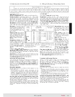
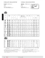
Albero motore
di acciaio C45; a
richiesta per grand. 63 ... 250 «Albero
motore bloccato assialmente» (sullo
scudo posteriore per grand. 63 ...
160S o anteriore per grand 160M
... 250), di serie (sullo scudo poste-
riore) per grand. 280, ved. cap. 3.6.
(2); estremità d’albero cilindriche con
linguetta forma A (arrotondata) e foro
filettato in testa (ved. tabella dove: d
= foro filettato in testa; b × h × l =
dimensioni linguetta).
Foro posterio-
re filettato
di estrazione in applica-
zioni con riduttore, di serie per grand.
90 ... 160S.
Steel
driving shaft
C45; on request
for sizes 63 ... 250 «Driving shaft
axially fastened» (on rear endshield
for sizes 63 ... 160S or front endshield
for sizes 160M ... 250), standard (on
rear endshield) for sizes 280, see
ch. 3.6. (2); cylindrical shaft ends
with A-shape (rounded) key and
tapped butt-end hole (see table,
where: d = tapped butt-end hole;
b × h × l = key dimensions).
Rear tapped hole
for dismounting
in applications with gear reducer, as
standard for sizes 90 ... 160S.
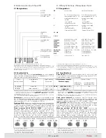
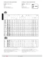
Housing
in pressure diecast light alloy (cast iron for size 200 with
in pressure diecast light alloy (cast iron for size 200 with
460 V 60 Hz motor supply); for mounting position IM B3: with
integral (sizes 280) or inserted feet (sizes 63 ... 250) which can be
mounted on
three sides
(sizes 90 ... 200).
Drive end
(
or flange
) and
non−drive end endshield
in cast iron or
light alloy (see following table).
«Supported» tightening attachments
of endshields and flanges
Carcassa
di lega leggera pressofusa (di ghisa per grand. 200 con ali-
mentazione motore 460 V 60 Hz); forma costruttiva IM B3 con piedi
integrali (grandezze 280) o riportati (grandezze 63 ... 250 ) montabili
su
tre lati
(grandezze 90 ... 200).
Scudo lato comando
(
o flangia
) e
lato opposto comando
di ghi sa
o di lega leggera (ved. tabella seguente).
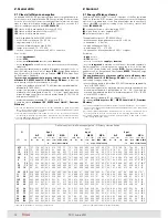
Scudi e flange con
attacchi di serrag gio «in appoggio»
e montati
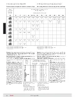
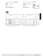
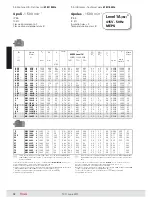
Dimensioni principali di accoppiamento delle forme costruttive con flangia
Main mating dimensions of the mounting positions with flange
Grand.
motore
Motor
size
Materiale scudi e cuscinetti
Endshield material and bearings
lato comando
drive end
lato opp. comando
non-drive end
63
LL 6202 2Z
6202 2Z LL
71
LL 6203 2Z
6203 2Z LL
80
LL 6204 2Z
6204 2Z LL
90
LL 6205 2Z
6205 2Z LL
100
LL 6206 2Z
6206 2Z LL
112
LL 6306 2Z
6306 2Z LL
132
LL
1)
6308 2Z
6308 2Z LL
160S
G 6309 2Z
6308 2Z LL
160M, 160L
G 6309 2ZC3
6309 2ZC3 G
180M
4)
LL
2)
6310 ZC3
6209 ZC3 LL
180L
4)
G 6310 ZC3
6210 ZC3 LL
200
4)
G 6312 ZC3
6210 ZC3 LL
225
G 6313 ZC3
6213 ZC3 G
250
G 6314 ZC3
6213 ZC3 G
280
G NU2217C3
3)
6314 ZC3 G
1) Forma costruttiva non disponibile per motore 112.
2) Forma costruttiva non disponibile per motore 132MA ... MC.
3) Forma costruttiva non disponibile per motore 160S.
* Motore a due poli.
1) Mounting position not available for motor 112.
2) Mounting position not available for motor 132MA ... MC.
3) Mounting position not available for motor 160S.
* Two poles motor.
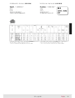
Forma
costruttiva
Mounting
position
Estremità d’albero - Shaft end Ø D x E
Flangia - Flange Ø P
Grandezza motore – Motor size
IM
63
71
80
90
100, 112
132
160
180
200
225
250
280
11 × 23
14 × 30
19 × 40
24 × 50
28 × 60
38 × 80
42 × 110
48 × 110
55 × 110
60 × 140
65 × 140
75 × 140
140
160
200
200
250
300
350
350
400
450
550
550
55 × 110*
60 × 140*
65 × 140*
450*
450*
550*
9 × 20
11 × 23
14 × 30
19 × 40
24 × 50
28 × 60
38 × 80
48 × 110
60 × 140
120
140
160
200
200
250
300
−
350
−
450
−
55 × 110*
3)
450*
−
−
−
−
19 × 40
200
1)
24 × 50
200
2)
−
−
−
−
−
−
11 × 23
14 × 30
19 × 40
28 × 60
38 × 80
−
−
−
−
−
−
120
140
160
−
200
250
−
11 × 23
120
14 × 30
140
19 × 40
160
−
−
−
−
−
−
−
−
19 × 40
−
−
−
−
160
−
−
−
−
−
−
−
2)
11 × 23
14 × 30
19 × 40
24 × 50
28 × 60
38 × 80
90
105
120
140
160
200
−
−
−
−
−
−
11 × 23
14 × 30
−
90
105
−
−
−
−
−
−
−
−
−
Summary of Contents for TX11 Series
Page 2: ......
Page 203: ...203 TX11 June 2011...