4-34
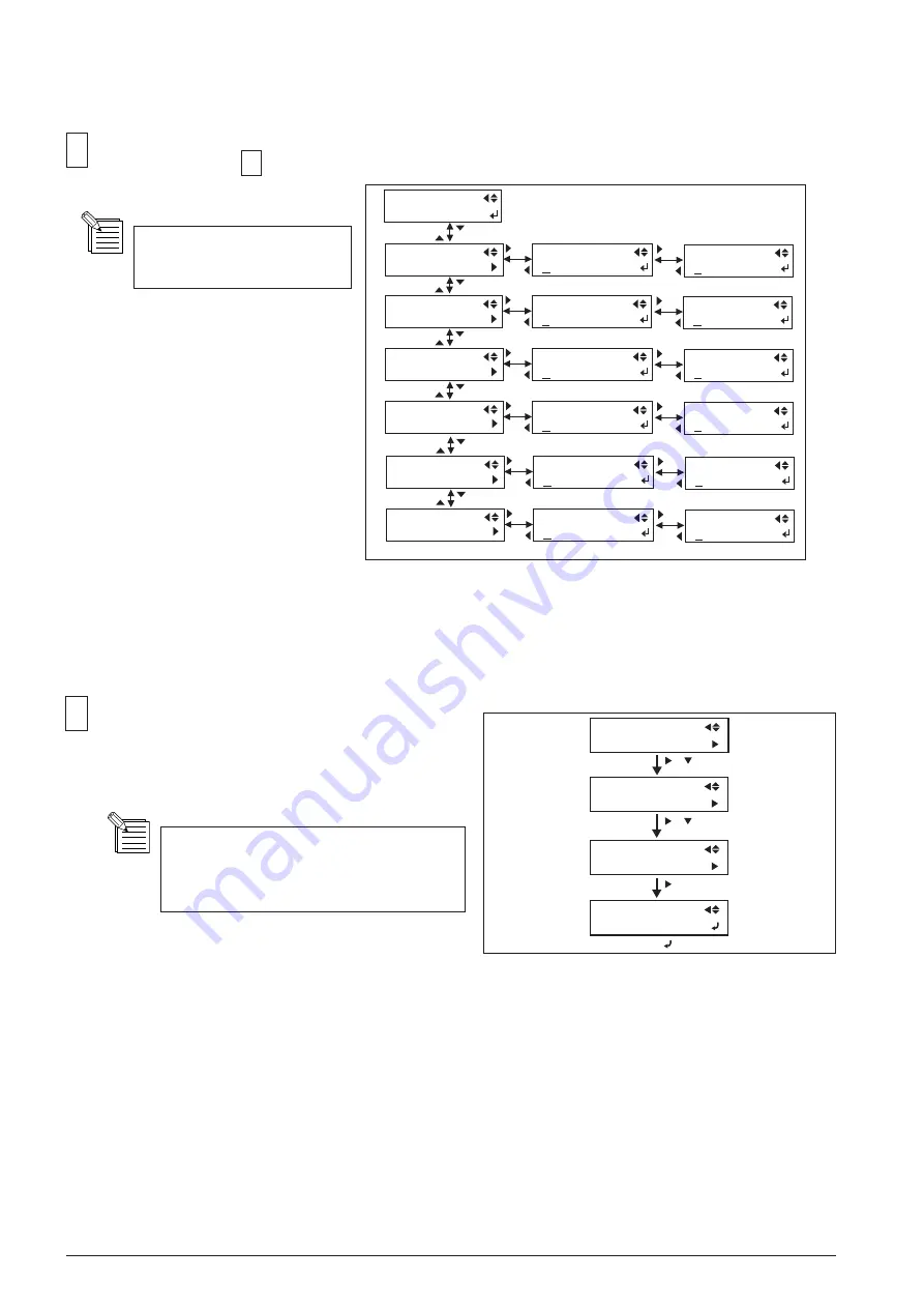
[ BIDIRECTIONAL ADJUSTMENT ]
Select [PRINT MENU] > [HEAD ADJUST] > [BI-DIR.
DEFAULT] > [TEST PRINT], and press the [ENTER]
key.
[ ]
SERVICE MENU
PRINT MENU
[ ]
[ ]
[ ]
PRINT MENU
HEAD ADJUST
HEAD ADJUST
BI-DIR.DEFAULT
BI-DIR.DEFAULT
TEST PRINT
[ ]
[ ]
21
If the head height is not [LOW], set it
to [LOW] and perform set up the media
again.
Select [DT1, Low], [DT3, Low], [DT1, High] and [DT3, High] in the [HEAD ADJUST] menu and enter the pa-
rameters checked at 19 with the Up and Down keys. Press the [ENTER] key to save the settings.
Parameters can be entered
with an increment of 1/2.
20
H1 H2 H3
2 1 3
HORIZONTAL
TEST PRINT
H1 H2 H3
2 1 3
H1 H2 H3
2 1 3
HORIZONTAL
DT1, Middle
HORIZONTAL
DT3, Middle
HORIZONTAL
DT1, Low
H1 H2 H3
2 1 3
HORIZONTAL
DT3, Low
H5 H6
2 1
H5 H6
2 1
H5 H6
2 1
H5 H6
2 1
H1 H2 H3
2 1 3
H1 H2 H3
2 1 3
HORIZONTAL
DT1, High
HORIZONTAL
DT3, High
H5 H6
2 1
H5 H6
2 1
Summary of Contents for VersaUV LEJ-640
Page 32: ...2 4 MAIN BOARD_Arrangement Diagram Soldering Side ...
Page 43: ...2 15 HEAD BOARD_Arrangement Diagram Soldering Side ...
Page 54: ...2 26 SERVO BOARD_Arrangement Diagram Soldering Side ...
Page 63: ...2 35 SUB BOARD B_ Arrangement Diagram Component Side ...
Page 70: ...2 42 2 6 INK SYSTEM BOARD INK SYSTEM_Arrangement Diagram Component Side ...
Page 282: ...4 74 9 Fix the I S Cover I S Cover Hook Screw Screw ...
Page 306: ...7 2 Unpacking ...


