Model menu
Flight modes
F X - 4 0
17.1 SELECTING FLIGHT MODES
The software of the FX-40 provides up to eight flight modes for
each individual model memory. This feature ensures that you
can always store the optimum settings for the various phases
of a typical flight, and call them up as and when required sim-
ply by operating a switch.
For example, this option can be used to program the settings
for a model glider so that the control surfaces are set correctly
for the winch launch phase, i.e. both ailerons and both flaps
lowered in order to gain maximum possible lift for the launch.
To guarantee a stable flight attitude you could also select the
option for setting an elevator offset to provide pitch trim com-
pensation (around the lateral axis). These values can be called
up prior to launching the model, using a switch or a particular
position of one transmitter control.
If you program several flight modes in a particular model
memory, it is possible to define the priority of the modes in any
way you like. Flight modes can be copied, named and rena-
med individually, and also erased individually. You can pro-
gram a delay time for each channel, so that there is a smooth
transition when you switch modes, rather than an abrupt
change.
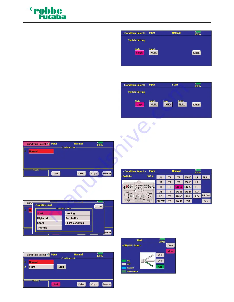
Mark the ‘Flight modes’ option in the Model menu. The screen
display now looks like this:
The basic programming procedure consists of the following
steps:
• Adding a new flight mode
Mark the ‘New’ field, and the screen displays a list of the
seven possible additional flight modes.
Mark the new flight mode you wish to add, in our case by
activating the ‘Start’ field. In the remainder of this section
we will cover the programming of this new mode.
Mark the field for selecting the flight mode switch (currently NONE).
In this sub-menu you can define the flight mode activation
switch, and its mode of operation. The following display is
used to define the switch mode:
Note that it is possible to select a switch which operates
completely normally (Separate) or a switch with a logical
function (Logic). Selecting the logical switch type enables
you to link the trigger process using a logical function. In
this case the following functions become available:
• AND: Links switches in series
• OR:
Links switches in parallel
• Ex-OR:
Links and connects particular switches
Activate the Switch Select menu to define the switch.
Select the switch you wish to use; it is marked both in the
list and in the schematic diagram of the transmitter.
The next step is to define the direction of switch operation
for activating and disabling this flight mode: this is done by
marking the ‘On-pos.’ field in the right column.
You can set the des-
ired switch mode
individually by tou-
ching the various
switch positions.
• Copying flight modes
Mark the ‘Copy’ field. This brings up the menu for copying
individual flight modes.
55


