Linkage Menu
F X - 4 0
16.8
SERVO CENTRE
SERVO CENTRE OFFSET
When you install the servos in a model, it is always best to
position them in such a way that the servo output arm is in the
neutral position when the trim control on the transmitter is also
at centre.
Sometimes the model’s restrictions make this impossible, and
in other cases the neutral position is non-standard due to the
use of different makes of servo. In such instances this function
can be used to bring the servos of all channels to the exact
neutral position.
This option should only be used to correct minor discrepan-
cies, as it inevitably affects servo travel, which may become
restricted and asymmetrical.
We recommend this procedure:
After establishing the correct trim positions through test-flying,
the first step should be to adjust the position of the servo out-
put arms as accurately as possible, and adjust the control sur-
face linkages to the correct mechanical trim settings. At this
stage the trim memory and the settings in this menu should be
left at 0%. Once you have made these adjustments as accura-
tely as possible, you should use this menu to fine-tune the
servo neutral positions to exact centre.
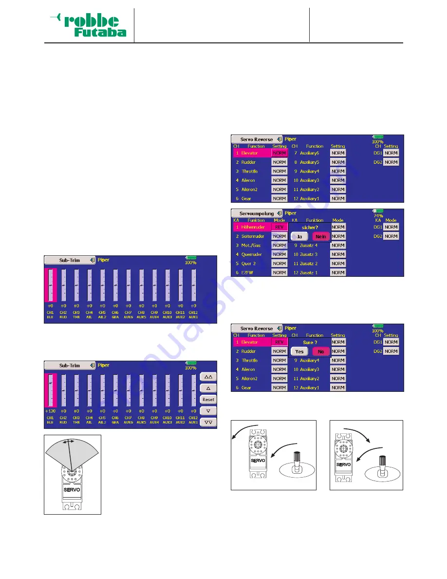
When you select the Servo Centre function, the screen display
looks like this:
The position of the servos for the first twelve channels is dis-
played both in bar form and as a percentage value, and each
channel is clearly identified. If you wish to make a change, the
first step is to mark the channel you wish to adjust.
The display now changes, and you will
see a column of buttons for changing
the setting at the right margin of the
screen. Pressing the single-arrow but-
tons causes the trim to change up or
down by one increment (step). Pres-
sing the double-arrow buttons changes
the setting by ten increments at a time.
The adjustment range is -120 to +240
increments, which corresponds to
about +/- 20° of servo travel. The
default setting is exactly 0 increments.
Once activated, each setting can be reset to the default value
(0 increments) by pressing the ‘Reset’ button.
16.9 SERVO REVERSE
This function is used to reverse the direction of servo rotation
electronically; it is available separately for all servos. This
means that you do not have to consider the direction of rota-
tion when installing the servos in a model. It is important to set
the correct direction of servo rotation using this function
before you start programming additional model data.
When you select the Servo Reverse function, the screen dis-
play looks like this (shown separately for fixed-wing models
and helicopters):
The current direction of rotation of the servos (NORM or REV)
is shown separately for all fourteen channels. You can reverse
any servo simply by activating the appropriate field. The chan-
nel is then marked, and a security query appears as shown in
the following illustration:
If you press the ‘YES’ button, the servo direction is reversed,
and the procedure is concluded.
This drawing shows the normal and reversed directions of
rotation of one servo.
45


