


Reference Manual Rev 1.13
004R-646-113
Page 9
3. Installation
3.1. Introduction
The following steps are required to set up the indicator.
Inspect indicator to ensure good condition.
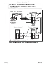
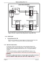
Use connection diagrams to wire up load cell, power and auxiliary cables as
required.
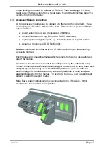
Insert any accessory modules that are being used.
Use the drill hole template provided for hole locations.
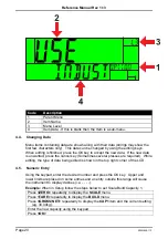
Connect Power to indicator and press
<POWER>
key to turn the instrument On.
Refer to the Setup Menus section on page 55 for information on configuring the
instrument.
To turn instrument OFF press and hold
<POWER>
key for three seconds (until
display blanks).
3.2. General Warnings
Indicator not to be subject to shock, excessive vibration or extremes of temperature
(before or after installation).
Inputs are protected against electrical interference, but excessive levels of electro-
magnetic radiation and RFI may affect the accuracy and stability.
The instrument
should be installed away from any sources of excessive electrical
noise.
The load cell cable is particularly sensitive to electrical noise and should be located
well away from any power or switching circuits.
For full EMC or for RFI immunity, termination of cable shields and correct earthing
of the instrument is essential.
3.3. Electrical Safety
For your protection all mains electrical hardware must be rated for environmental
conditions of use.
Pluggable equipment must be installed near an easily accessible power socket
outlet.
To avoid the possibility of electric shock or damage to the instrument, always switch
off or isolate the instrument from the power supply before maintenance is carried
out.
3.4. Cleaning
To maintain the instrument, never use harsh abrasive cleaners or solvents. Wipe
the instrument with a soft cloth
slightly
dampened with warm soapy water.
3.5. Panel Mount Template
The panel mount template is supplied with the instrument. It shows the location of
the rectangular cut-out and the four mounting screws.
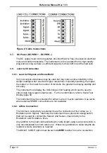
3.6. Cable Connections
All cable connections are made to the rear of the instrument using pluggable screw
terminals. It is not necessary to tin the ends of the wires with solder or to add crimp
ferrules to the wires, however, these techniques are compatible with the terminals.


