


Reference Manual Rev 1.13
004R-646-113
Page 11
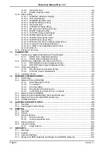
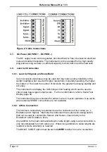
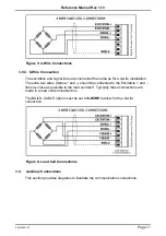
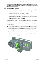
Figure 3: 4-Wire Connections
3.8.3. 6-Wire Connection
The excitation and signal lines are connected the same as for a 4-wire installation.
The extra two wires (Sense + and –) should be connected to the Exci and –
lines as close as possible to the load cell itself. Typically these connections are
made in a load cell termination box.
The BUILD: CABLE option must be set to
6-WIRE
to allow for true 6-wire
connection.
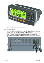
Figure 4: Load Cell Connections
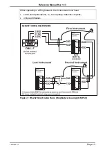
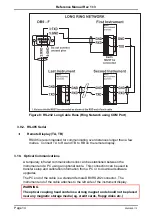
3.9. Auxiliary Connections
This section provides diagrams to illustrate the communication connections.


