


Reference Manual Rev 1.13
Page 10
004R-646-113
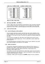
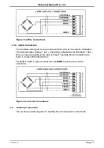
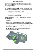
Figure 2: Cable Connections
3.7. DC Power (DC PWR + , DC PWR –)
The DC supply need not be regulated, provided that it is free of excessive electrical
noise and sudden transients. The instrument can be operated from a high quality
plug-pack as long as there is sufficient capacity to drive both it and the load cells.
3.8. Load Cell Connection
3.8.1. Load Cell Signals and Scale Build
Very low output scale bases may be used but may induce some instability in the
weight readings when used with higher resolutions. Generally speaking, the higher
the output, or the lower the number of divisions, the greater the display stability and
accuracy.
The
instrument
can display the milli-Volt-per-Volt reading which can be used to
check scale base signal output levels. For more information, refer to Scale Test
Display page 59.
The
instrument
may be connected for either 4-wire or 6–wire operation. Use 4-wire
when external SENSE connections are not available.
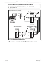
3.8.2. 4-Wire Connection
The minimum connectivity requirements are the connection of four wires (i.e. ±
Excitation and ± Signal). Internally the
instrument
has a precision analog switch
that can be used to connect the Sense+ and Sense– lines directly to the
Exc and Excitation– lines.
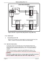
Any addition to the load cell manufacturer's cable length using 4-wire connection is
only recommended for short cable runs. Where long additions to cable lengths are
needed, a 6-wire extension is required.
The BUILD: CABLE option must be set to
4-WIRE
to allow for 4-wire connection.


