20 June 2005
SERVICE PROGRAM MODE TABLES
5-7
Service
Tables
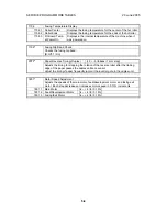
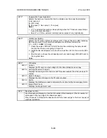
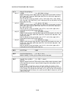
SP2-xxx: Drum
2001
*
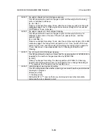
Charge Roller Bias Adjustment
Copying
[–1000 ~ –2000 /
–1500V
/ 10V step]
2001 1*
Adjusts the voltage applied to the charge roller for copying.
ID Sensor Pattern
[0 ~ 700 /
250V
/ 10V step]
2001 2*
Adjusts the voltage applied to the charge roller when making the VSDP ID sensor
pattern (for charge roller voltage correction). The actual charge roller voltage is
this value plus the value of SP2001 1.
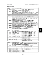
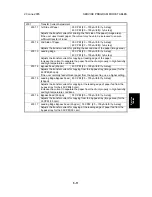
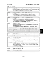
2005*
Charge Roller Bias Correction
Charge Roller Voltage Correction 1
[0.1 ~ 1.0 /
0.85
/ 0.05 step]
2005 1*
Adjusts the lower threshold value for the charge roller correction.
When the value of VSP/VSG is greater than this value, the charge roller voltage
increases by 30 V (e.g., from –500 to –530).
Charge Roller Voltage Correction 2
[0.1 ~ 1.0 /
0.90
/ 0.05 step]
2005 2*
Adjusts the upper threshold value for the charge roller correction.
When the value of VSP/VSG is greater than this value, the charge roller voltage
decreases by 30 V (absolute value).
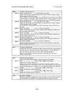
Charge Roller Voltage Adjustment 1
[–1000 ~
–
2000 /
–1500V
/ 10V step]
2005 3*
Adjusts the lower limit value for charge roller voltage correction.
Charge Roller Voltage Adjustment 2
[–1000 ~
–
2000 /
–2000V
/ 10V step]
2005 4*
Adjusts the upper limit value for charge roller voltage correction.
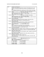
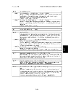
Charge Roller Voltage Step
[0 ~ 100V /
30V
/ 10V step]
2005 5*
Adjusts the correction voltage adjustment step size.
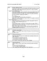
Printing Erase Margin
2101
*
Adjusts the leading edge (top), trailing edge (bottom), left, and right margins
2101 1* Leading Edge (Top)
[0.9 ~ 9.0 /
3
/ 0.1 mm step] Spec:
±
2 mm
2101 2* Trailing Edge (Bottom)
[0.9 ~ 9.0 /
3
/ 0.1 mm step] Spec:
±
2 mm
2101 3* Left Edge
[0.9 ~ 9.0 /
2
/ 0.1 mm step] Spec:
±
1.5 mm
2101 4* Right Edge
[0.9 ~ 9.0 /
2
/ 0.1 mm step] Spec:
±
1.5 mm
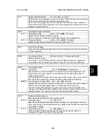
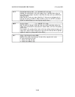
2101 5* Trailing Edge - Back side
[0.0 ~ 4.0 /
1.2
/ 0.1 mm step]
Recommended: 2
±
1.5 mm
2101 6* Back Side - Right
[0.0 ~ 9.0 /
4.0
/ 0.1 mm step]
Recommended:
2
±
1.5 mm
2101 7* Back Side - Left
[0.0 ~ 9.0 /
4.0
/ 0.1 mm step]
Recommended: 2 +2.5/-1.5 mm
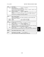
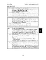
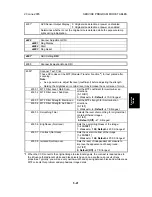
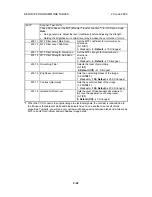
LD Power Adjustment
DFU
2103
*
Adjusts the intensity of the laser for the copier, printer, and fax unit. The Copier
and Printer/Fax settings can be adjusted separately.
2103 1* LD1 (Copier)
35 cpm: [–30~+64/–10/1 LSB step
45 cpm: [–30~64/5/1 LSB step]]
2103 2* LD2 (Copier)
35 cpm: [–30~+79/–30/1 LSB step
45 cpm: [–30~79/–25/1 LSB step]]
2103 3* LD1 (Printer, FAX)
[–50 ~ –35 /
–25
/1 LSB step]
2103 4* LD2 (Printer, FAX)
[–50 ~ –35 /
–25
/1 LSB step]
2103 5* LD1 Adjustment Start/End
OFF/ON
2103 6* LD2 Adjustment Start/End
OFF/ON


