IMAGE FUSING AND PAPER EXIT
20 June 2005
6-92
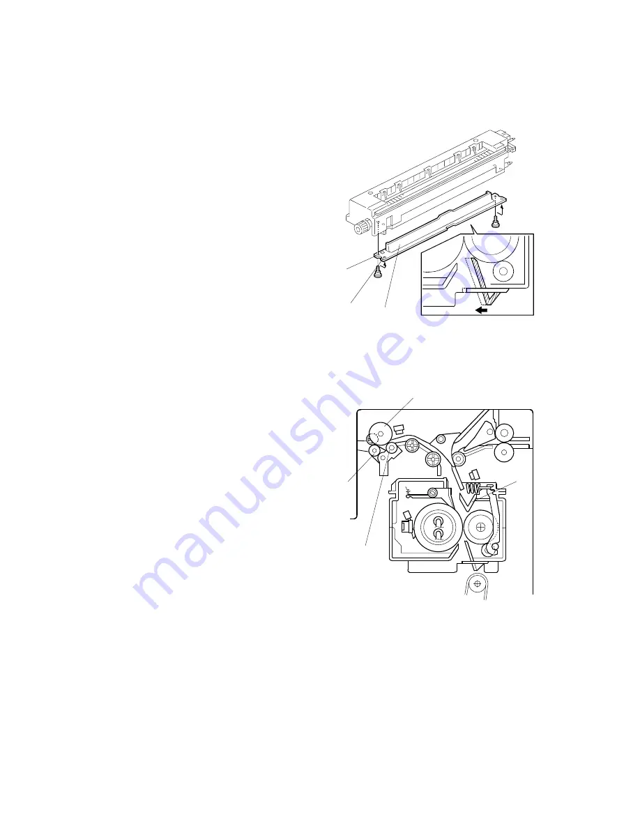
6.15.4 FUSING ENTRANCE GUIDE SHIFT MECHANISM
The entrance guide [A] has two holes on
each side to adjust for paper thickness to
prevent creasing. Normally, the left screw
hole [C] on each side is used.
For
thin
paper, use screw holes [B] to
move the entrance guide to the left. This
setting allows more direct access to the
gap between the hot and pressure rollers,
and prevents thin paper from buckling
against the hot roller which can cause
blurring at the leading edge of the copy.
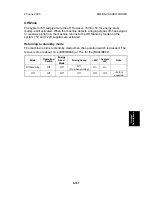
6.15.5 EXIT GUIDE PLATE AND DE-CURLER ROLLERS
The exit guide plate [A] also functions as a
pressure roller stripper. The exit guide
plate can be moved in order to remove
jammed paper.
Stacking has been improved by mounting
a face-curl correction mechanism at the
paper exit roller.
Two de-curler rollers [B] and [C] have been
added under the exit roller [D] to correct
the curl that paper acquires during
transport through the fusing unit.
B195D979.WMF
B195D980.WMF
[A]
[B]
[C]
[C]
[D]
[B]
[A]


