LASER UNIT
20 June 2005
3-28
Laser beam pitch adjustment
After replacing the LD board, perform the laser beam pitch adjustment. There are
two laser beam pitch adjustment procedures: one for 400 dpi, and one for 600 dpi.
These adjustments use the following SP modes.
SP2-110
Test Mode Dpi (0: 400 dpi, 8: 600 dpi)
SP2-109-1:
LD Beam Pitch Adjustment – 400 dpi
SP2-109-2:
LD Beam Pitch Adjustment – 600 dpi
SP2-109-3:
LD Initial Setting – 400 dpi
SP2-109-4:
LD Initial Setting – 600 dpi
1. Set SP2-110 to 0 (for 400 dpi), or to 8 (for 600 dpi).
2. Do SP 2-109-8 to reset all the beam pitch data.
3. For SP2-109-1 input 144.
NOTE:
The entry “144” is only a starting reference value that will allow the
machine to operate. It is only a starting point for adjustment.
4. Do SP2-109-3.
5. Print the test pattern onto A3 (11" x 17") paper using SP2-902-3 No. 12.
( 5.2.3 Test Pattern Printing (SP2-902).
6. On the test pattern write 144, the value of SP2-109-1.
7. Change the value of SP2-109-1 and then print another test pattern, repeating
steps 2 to 6. Print about 5 patterns with different values for SP2-109-1 (e.g. 48,
96, 192, 240).
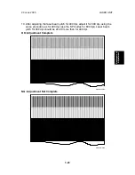
8. Check these test patterns. If the laser beam pitch is not correct, the image
looks like a black vertical stripe pattern.
NOTE:
For example, if the pattern made with the value 192 has fewer obvious
stripes than the other printouts, the correct value is near 192.
9. Fine adjustment: Do steps 2 to 6 to adjust the laser beam pitch position until
thin lines are of uniform thickness (no stripes should appear on the printout).
NOTE:
In step 3, input a value estimated to be correct (e.g., if 192 was the
closest, try 182), then do steps 4 and 5, then if necessary go back to
step 2 and try another value.

