25
1.800.627.4499
Integral Indirect Gas-Fired Heat Module
OPTION
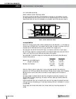
4.4 HEAT MODULE PRESSURE DROP
For every heat module, the airflow through the module encounters resistance and this produces
a drop in pressure between the inlet side and the outlet side. The greater the airflow through
the module, the greater the pressure drop from one side of the module to the other.
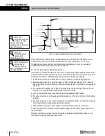
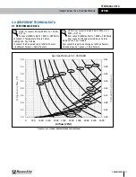
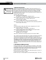
To determine the pressure drop across a module, use the Temperature and Pressure chart
shown in section 4.1 of this manual. Find the airflow in cfm, shown at the bottom of the chart.
Follow the grid line up until it intersects with the Pressure Drop line for the desired module. Use
the example shown in Section 4.2 of this manual as an illustration.
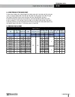
4.5 MODULE DATA CHART
Temperature Rise
Unit
No. of
Tubes
Input Rate
Output
Temperature Rise
Air Flow @ Nom.
Duct Opening
Vent
Diameter
Gas Train
NPT
Weight–
Installed
Model No.
Qty
Btu/h
Btu/h
Min.
Max.
Min.
Max.
“D”
inch
lb
˚F
˚F
CFM
CFM
inch
HM-050
3
50,000
40,000
20
60
617
1,852
5
1/2
87
HM-075
3
75,000
60,000
926
2,778
1/2
87
HM-100
4
100,000
80,000
1,235
3,704
1/2
97
HM-125
5
125,000
100,000
1,543
4,630
3/4
114
HM-150
6
150,000
120,000
1,852
5,556
3/4
125
HM-200
8
200,000
160,000
2,469
7,407
6
3/4
145
HM-250
10
250,000
200,000
3,086
9,259
3/4
180
HM-300
12
300,000
240,000
3,704
11,111
3/4
201
HM-350
14
350,000
280,000
4,321 12,963
3/4
231
TECHNICAL DATA


